

Electronic device, electronic apparatus, and moving object
a technology of electronic equipment and moving objects, applied in the direction of piezoelectric/electrostrictive/magnetostrictive devices, electrical apparatus, piezoelectric/electrostriction/magnetostriction machines, etc., can solve the problems of increasing power consumption of oscillators, difficult to maintain a constant temperature of quartz crystal resonators, etc., to achieve stable characteristics and low power consumption
- Summary
- Abstract
- Description
- Claims
- Application Information
AI Technical Summary
Benefits of technology
Problems solved by technology
Method used
Image

Examples
first embodiment
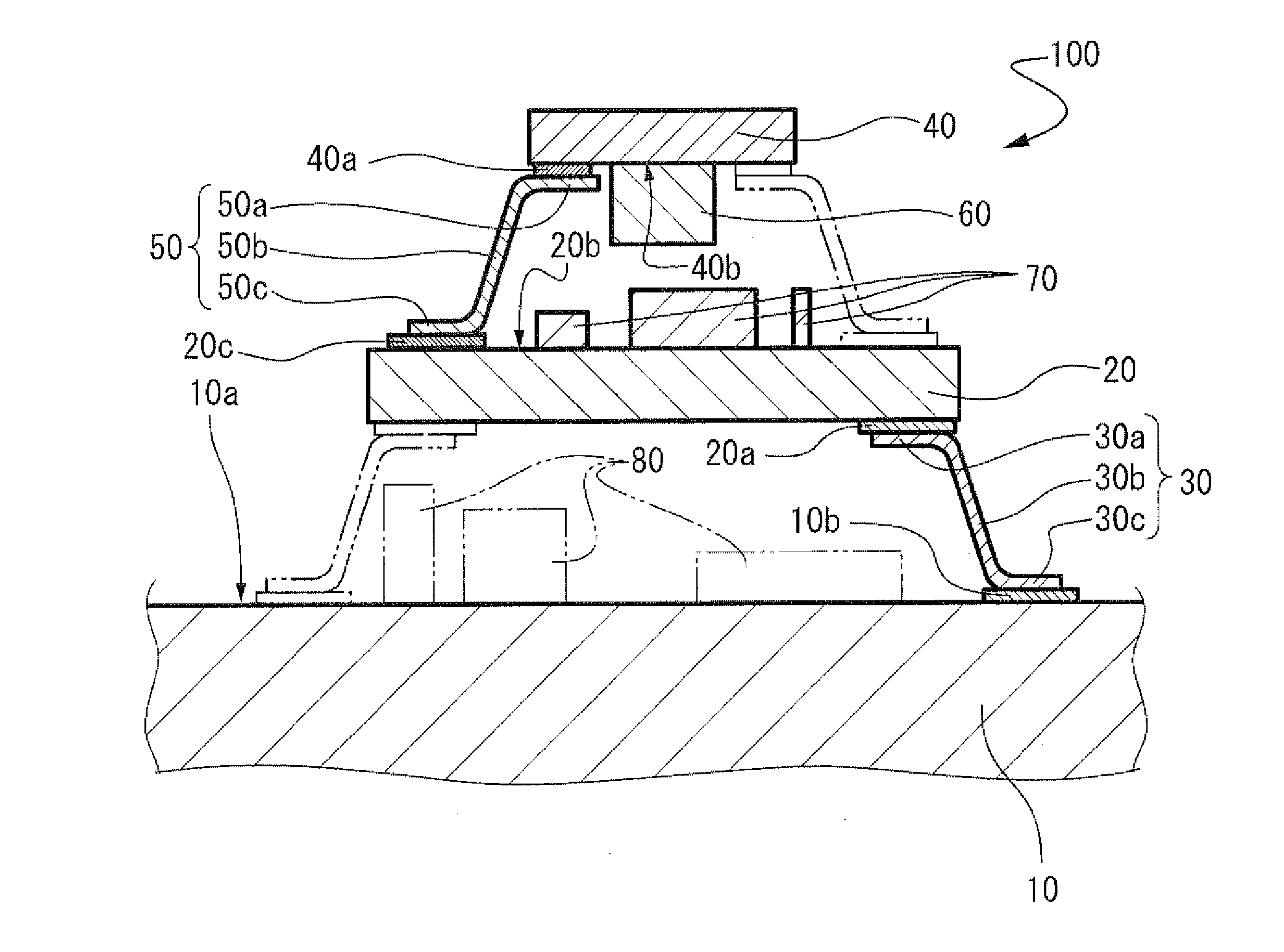
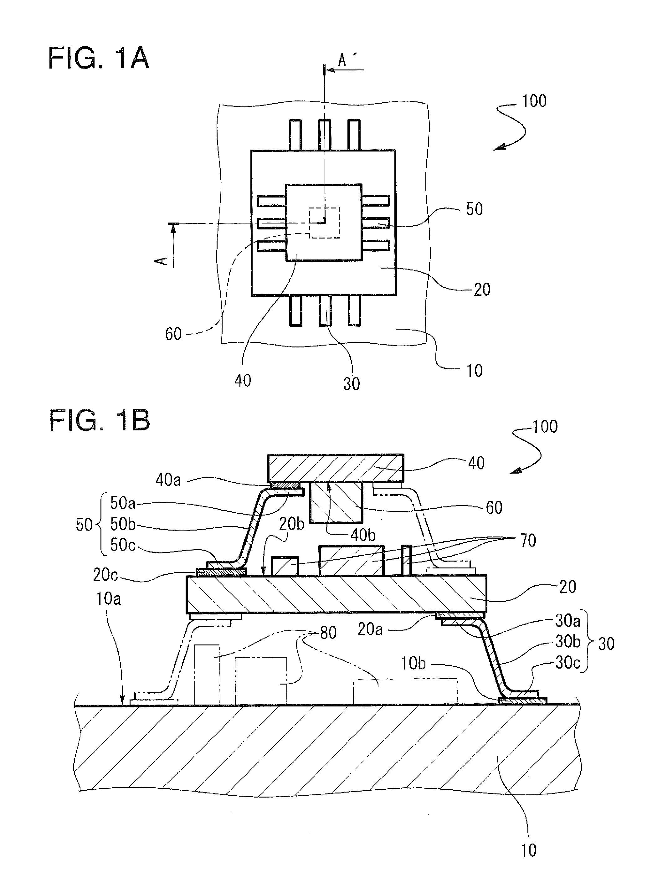
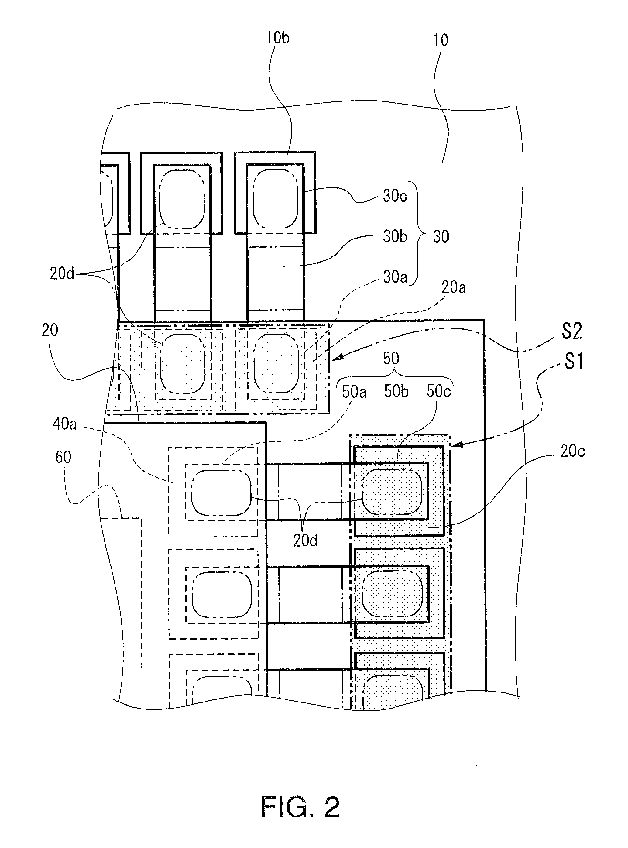
[0033]An electronic device according to a first embodiment is shown in FIGS. 1A and 13, in which FIG. 1A is a plan view and FIG. 1B is a cross-sectional view taken along line A-A shown in FIG. 1A. As shown in FIG. 1B, an electronic device 100 is provided with a substrate lead 30 as a second support which supports a substrate 20 on an upper surface 10a of a base 10 and the substrate 20 is supported on and fixed to the base 10. A plurality of substrate leads 30 is connected to the substrate 20, as shown in FIG. 1A, and each substrate lead 20 is provided with a substrate lead connection portion 30a which is connected to an external terminal 20a of an electrode wiring disposed on the substrate 20, a substrate lead base connection portion 30c which is connected to a base electrode wiring terminal 10b (hereinafter referred to as a base terminal 10b) of the base 10, and a substrate lead holding portion 30b which holds the substrate 20 at a distance from the upper surface 10a of the base 10...
second embodiment
[0057]As a second embodiment, an electronic apparatus will be described which is provided with any one of the electronic devices 100, 110, 120, 130, and 140 according to the first embodiment. FIG. 5 is a perspective view showing a mobile type (or notebook type) personal computer as the electronic apparatus according to the second embodiment. A personal computer 1000 shown in FIG. 5 is provided with a main body section 1200 provided with a keyboard 1100, and a display unit 1400 provided with a display section 1300. The display unit 1400 is held so as to be able to rotate with respect to the main body section 1200 through a hinge structure section. Then, the personal computer 1000 has any one of the electronic devices 100, 110, 120, 130, and 140 built-in as an oscillator for a reference signal or a reference clock.
[0058]FIG. 6 is a perspective view showing a mobile phone (also includes a PHS) as the electronic apparatus according to the second embodiment. A mobile phone 2000 shown in ...
third embodiment
[0062]FIG. 8 is a perspective view showing an automobile as a moving object which is provided with the electronic device 100, 110, 120, 130, or 140 according to the first embodiment. In an automobile 6000 shown in FIG. 8, an electronic control unit 6100 having the electronic device 100, 110, 120, 130, or 140 according to the first embodiment built-in is mounted on a car body 6200. The electronic control unit 6100 is applied as a control unit of, for example, a keyless entry, an immobilizer, a car navigation system, a car air conditioner, an antilock brake system (ABS), an airbag, a tire pressure monitoring system (TPMS), an engine control, a battery monitor of a hybrid car or an electric car, a car body attitude control system, or the like.
[0063]The electronic device, the electronic apparatus, and the moving object according to the embodiments described above are not limited thereto and the configuration of each section can be replaced with any configuration having the same function...
PUM
 Abstract
Description
Claims
Application Information