Method, lens assembly and camera for reducing stray light

a technology of lens assembly and camera, which is applied in the field of method, lens assembly and camera for reducing stray light, can solve the problems of unsatisfactory changes in the pixel level of the image being captured, and achieve the effects of accurate control of aperture gate characteristics, high resolution, and easy modification of shape, position and size of aperture ga

Active Publication Date: 2014-10-30
AXIS
View PDF3 Cites 15 Cited by
  • Summary
  • Abstract
  • Description
  • Claims
  • Application Information

AI Technical Summary

Benefits of technology

[0046]According to another embodiment of the invention, said aperture unit may comprise a rotating disk having a first gate and a second gate corresponding to different positions and / or shapes of said aperture gate in said aperture plane, which is advantageous in that different aperture gate settings may be realized in a mechanically simple but yet reliable manner. The rotating disk may thus be rotated in such a way that different gates are rotated into a position where a specific gate is used to control the amount and characteristics of the light reaching e.g. the detector of a camera. Additionally, the rotating disk may be so designed that a size of the aperture gate may additionally be controlled. In order to realize this a rotating disk having a plurality of aperture gates, corresponding to different positions, shapes and / or sizes may be used.
[0047]According to an embodiment of the invention, said aperture unit may comprise a liquid crystal element adapted to transmit or block light in a first position in said aperture plane and in a second position in said aperture plane corresponding to different positions and shapes of said aperture gate in said aperture plane. By comprising a liquid crystal element in the aperture gate, the aperture gate may be realized in a way where both the shape, position and the size of the aperture gate may easily be altered, as the pixels of the liquid crystal element is activated or deactivated in order to make the pixels light blocking or semitransparent. When the pixels are not activated or vice versa the liquid crystal element may be transparent. Depending on the resolution of the liquid crystal element the position, shape and size of the aperture gate may be controlled in a more or less exact manner, which means that by utilizing a liquid crystal element having a high resolution, the characteristics of the aperture gate may be accurately controlled.
[0048]According to an embodiment of the invention, said aperture unit may comprise a movable conventional iris for achieving said aperture gate and being adapted to be adjusted into different positions in said aperture plane, which is advantageous in that the position and size of the aperture gate may be adjusted in a simple and reliable manner.

Problems solved by technology

For instance, unwanted features of a camera system may result in undesired changes of the pixel levels in the image being captured.

Method used


Image

  • Method, lens assembly and camera for reducing stray light
  • Method, lens assembly and camera for reducing stray light
  • Method, lens assembly and camera for reducing stray light

Examples


Embodiment Construction

[0062]The present invention will now be described more fully hereinafter with reference to the accompanying drawings, in which currently preferred embodiments of the invention are shown. This invention may, however, be embodied in many different forms and should not be construed as limited to the embodiments set forth herein; rather, these embodiments are provided for thoroughness and completeness, and fully convey the scope of the invention to the skilled person. Like reference characters refer to like elements throughout.

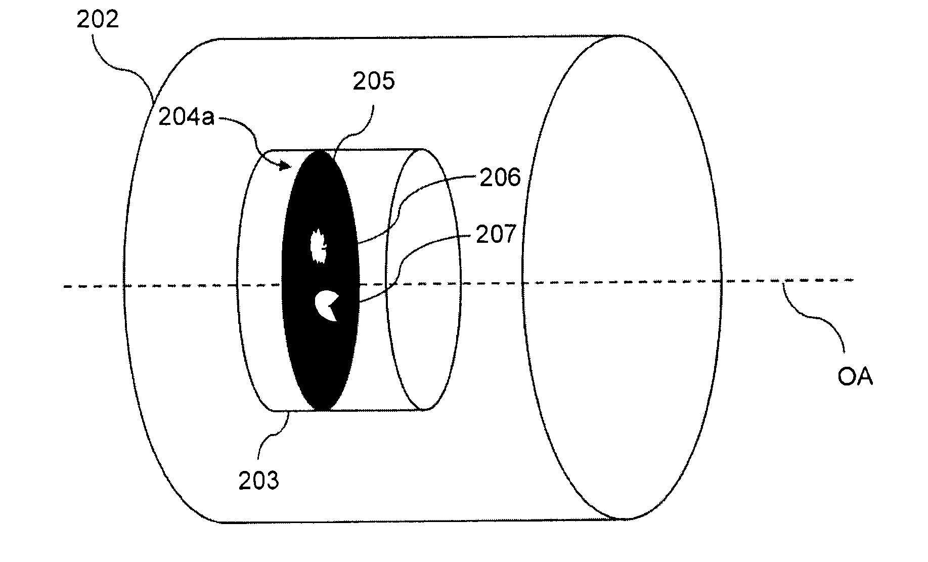
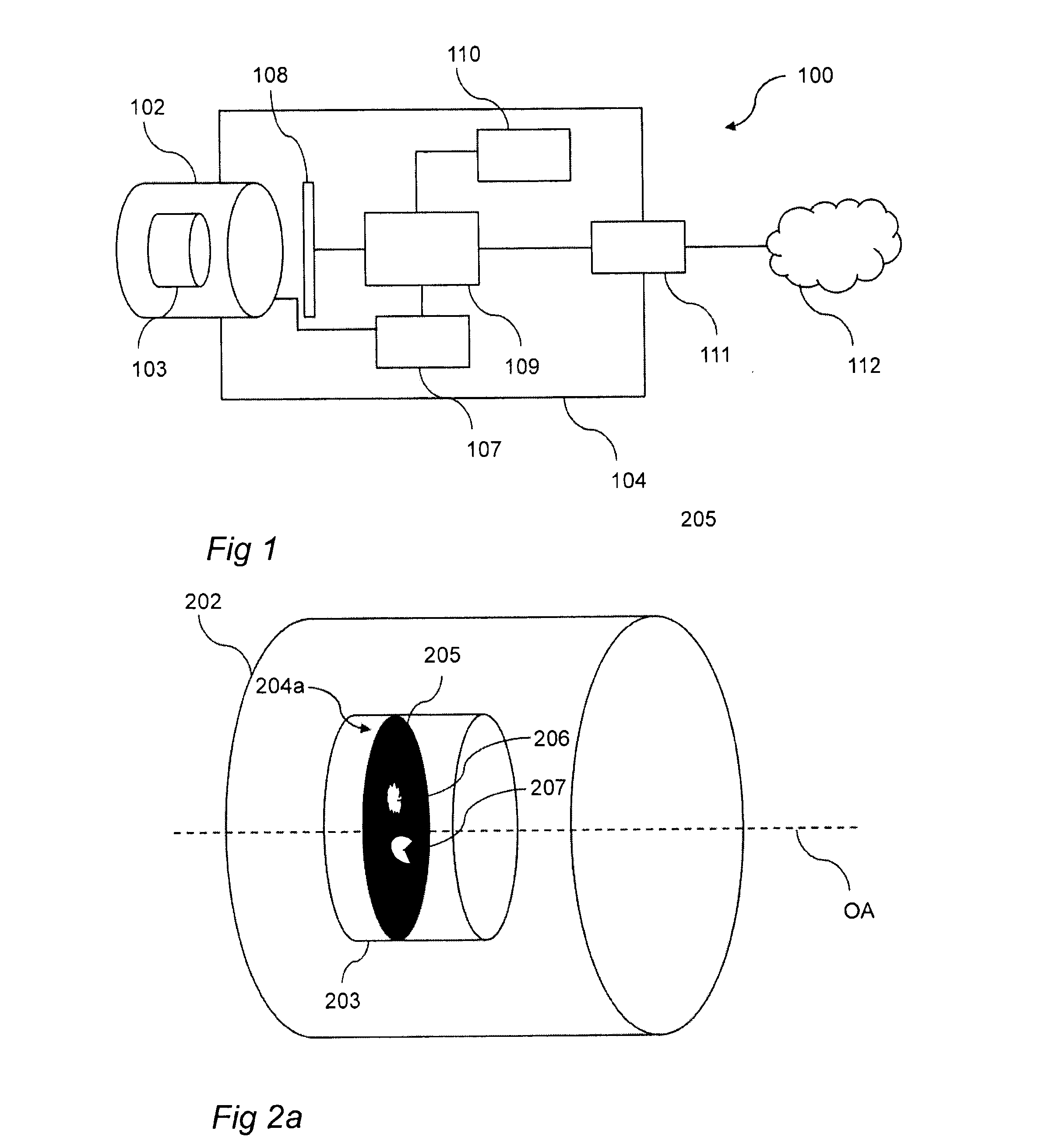
[0063]Referring now to the drawings and to FIG. 1 in particular, there is conceptually depicted a digital video camera 100 employed with a lens assembly 102 according to an embodiment of the invention. The lens assembly 102 is equipped with an aperture unit 103. The digital video camera 100 includes a focusing function, i.e. the focus of the digital video camera 100 may be varied to focus on objects on different distances from the camera. Moreover, the digital vid...


PUM


Abstract

The present invention relates to a method (300) for reducing stray light in an output image of a scene, said method comprising; providing (301) a camera (100) comprising a lens assembly (102, 202), providing (302) an aperture unit (103, 203) having an aperture gate (204a, 204b) in an aperture plane being orthogonal to an optical axis (OA) of said lens assembly (102, 202), said aperture gate (204a, 204b) being adjustable in said aperture plane, acquiring (303), by means of said camera (100), a plurality of images of said scene, wherein each image of said plurality of images is acquired using an unique aperture gate setting, wherein each of said unique aperture gate settings correspond to a unique combination of a position and a shape of said aperture gate (204a, 204b) in said aperture plane, analyzing (305) said plurality of images for generating data pertaining to a difference in stray light content with respect to said plurality of images, and producing (306) said output image based on said data pertaining to said difference in stray light content.

Description

TECHNICAL FIELD[0001]The present invention generally relates to a method for reducing stray light in an output image of a scene. The invention also relates to a lens assembly for reducing stray light and a camera having such a lens assembly and a processing unit arranged to perform the method. Further, the invention also relates to a system comprising a camera and a processing unit arranged to perform the method. The camera of the system comprises a lens assembly for reducing stray light. Furthermore, the invention also relates to a use of the camera and the system.BACKGROUND ART[0002]Cameras are used in a large variety of applications in order to capture and record still pictures and video streams. In order to capture or record an image or a video stream, light originating from the scene to be captured is collected using some form of lens system of the camera in question. The light originating from the scene is then focused by means of the lens system and the focused light is direc...

Claims


Application Information

Patent Timeline
Patent Type & Authority Applications(United States)
IPC IPC(8): H04N5/235
CPCH04N5/2351H04N5/2355H04N23/743H04N23/75H04N23/55H04N23/69H04N23/76H04N23/741H04N23/71
Inventor HJELMSTROM, JONASJOHANNESSON, ANDERS
Owner AXIS
Why Eureka
Try Eureka