X-Ray Detection Apparatus

a detection apparatus and x-ray technology, applied in the field of x-ray detectors, can solve the problems of more difficult fabrication in large areas, and the x-ray incident in these regions will pass through unperturbed

Inactive Publication Date: 2014-10-30
IBEX INNOVATIONS
View PDF3 Cites 10 Cited by
  • Summary
  • Abstract
  • Description
  • Claims
  • Application Information

AI Technical Summary

Benefits of technology

[0066]The detector of the invention, which is an indirect detector, provides for materials identification of objects combined with high reso...

Problems solved by technology

The general trend in imaging has been to eliminate scintillator energy response as they result in shadows in the image, which is generally regarded as undesirable.
However, it is more difficult...

Method used


Image

  • X-Ray Detection Apparatus
  • X-Ray Detection Apparatus
  • X-Ray Detection Apparatus

Examples


first embodiment

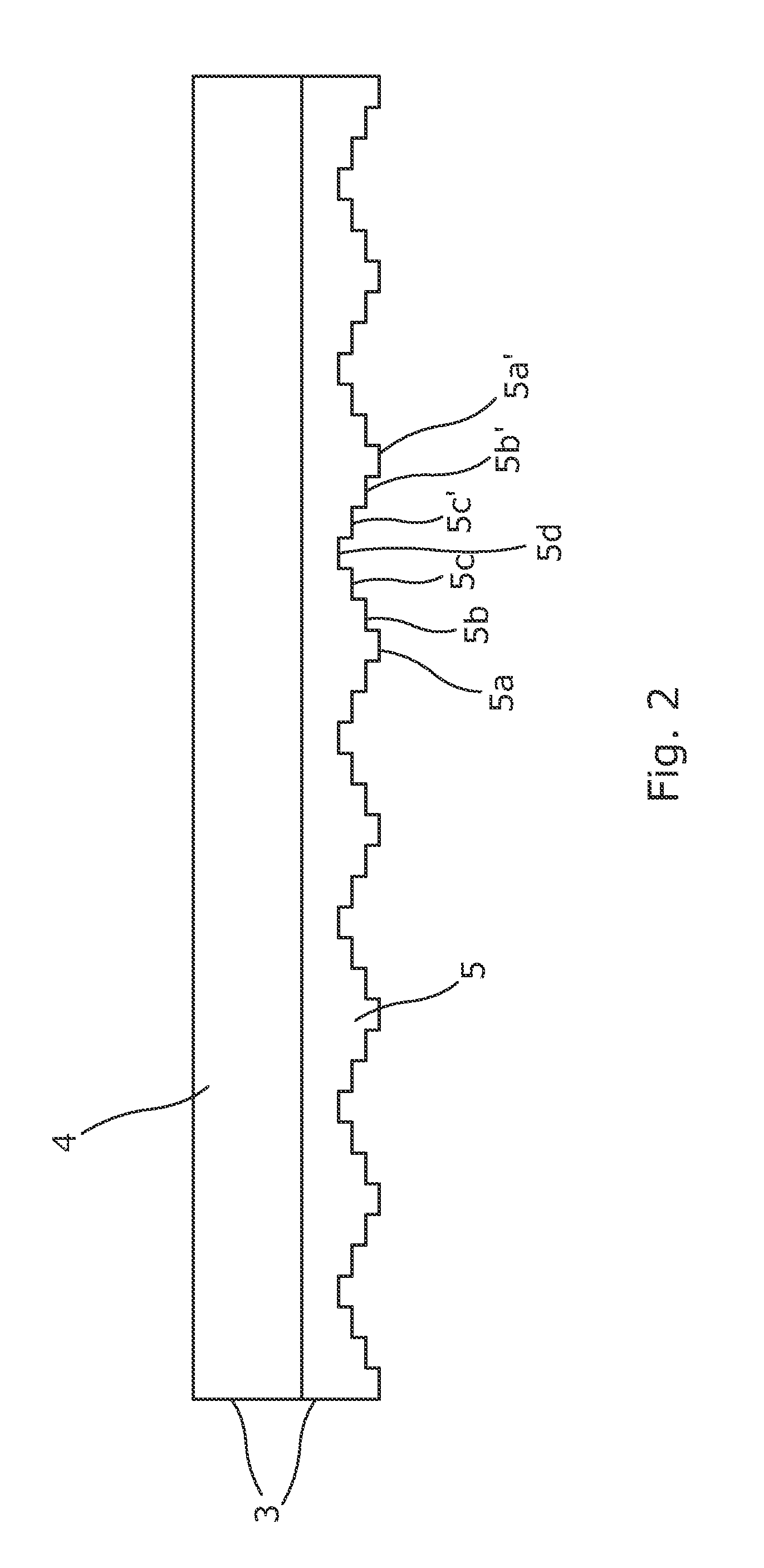
[0093]FIG. 2 illustrates in cross-section a scintillator plate 3 which comprises a scintillator layer 4 and a backing layer 5. The scintillator layer 4 is of a uniform material and has a uniform thickness. Preferably, the material from which the scintillator layer 4 is formed has a strong response to incident x-ray photon energy. However, the backing layer 5, comprises a multiplicity of regions of differing thickness represented by numerals 5a to 5d. For the sake of clarity only a sample of regions are numbered.

second embodiment

[0094]FIG. 3 illustrates in cross-section a scintillator plate 3 which again comprises a scintillator layer 4 and a backing layer 5. However, in this embodiment the metal (aluminium) backing layer is of a uniform material and a uniform thickness, whereas the scintillator layer 4 comprises a multiplicity of regions of differing thicknesses represented by the numerals 4a to 4d. For the sake of clarity only a sample of regions are numbered. Preferably, the material from which the scintillator layer 4 is formed has a strong response to incident x-ray photon energy.

[0095]FIG. 4 is a rear view of the scintillator plate illustrated in FIG. 2 and a front view of the scintillator plate illustrated in FIG. 3. The plate 3 provides forty nine regions, based around a repeating array of nine different pixel thicknesses, formed in a three by three block of regions. This arrangement provides that for any three by three group of nine regions the central pixel of the group is surrounded by eight regi...


PUM


Abstract

X-ray imaging apparatus,which includes an x-ray detector. The x-ray detector comprises a member configured to convert incident x-ray wavelength photons into emitted visible wavelength photons, a position for a material under test, an x-ray source, and a structure configured to perturb an x-ray energy spectrum, each lying on a common axis. The x-ray source is arranged to direct an x-ray energy spectrum along the common axis to impinge upon the member, the structure configured to perturb the x-ray energy spectrum, and positioned material under test. The structure lies between the x-ray source and the member to one side of the position for material under test intersecting the common axis, and the said structure comprises at least three adjacent regions, each region different to immediately adjacent regions and configured to perturb the x-ray energy spectrum differently.

Description

FIELD OF THE INVENTION[0001]The present invention relates to x-ray detectors and in particular to x-ray detectors including a scintillator.BACKGROUND OF THE INVENTION[0002]An x-ray tube outputs radiation across a wide range of energy bands, the distribution of the energy being defined by the accelerating voltage applied to the tube. When x-rays impact a material, they are absorbed as they pass through. X-rays of different energies are absorbed differently which means that the initial x-ray intensity profile changes. Different materials cause a distinctive change in shape of the x-ray intensity spectra and thus if the spectra can be recorded with sufficient accuracy, it is possible to predict the material that the x-rays have passed through.[0003]While the mass absorption coefficient depends upon both the material type and also the energy of the incident photons, the mass absorption coefficient is independent of material thickness and density. Hence, faced with a resultant spectrum, ...

Claims


Application Information

Patent Timeline
IPC IPC(8): G01T1/20G01N23/04
CPCG01N23/04G01T1/20G01T1/2985G01N23/087G01T1/202G01T1/362
Inventor GIBSON, GARY
Owner IBEX INNOVATIONS
Why Eureka
Try Eureka