Arrangement to control the clearance of a sliding bearing

a technology of sliding bearing and clearance, which is applied in the direction of hydrostatic bearings, bearing cooling, machines/engines, etc., can solve the problems of insufficient thickness of lubricating layer, damage to the electrical generator of wind turbines, and insufficient rolling element bearings, etc., and achieve the effect of reducing the amount of heat los

Active Publication Date: 2014-10-30
SIEMENS GAMESA RENEWABLE ENERGY AS
View PDF3 Cites 14 Cited by
  • Summary
  • Abstract
  • Description
  • Claims
  • Application Information

AI Technical Summary

Benefits of technology

[0021]It is the aim of the disclosed to provide an improved method to control the clearance of the bearing.

Problems solved by technology

In an arrangement, where higher loads act and higher moments have to be transferred over the bearing, rolling element bearings are not sufficient.
This might lead to a contact between the rotor and the stator and thereby to damages in the electrical generator of the wind turbine.
When the clearance of the main bearing is too low, layer of lubrication might not have a sufficient thickness and the friction in the bearing is too high.
This results in damages in the bearing and a reduced live-time of the bearing components.
A too low clearance in the bearing causes a rise in the temperature of the bearing components due to higher friction.
In addition it reduces the circulation and exchange of the lubricant in the bearing.
This shows the disadvantage that the reaction of the cooling system on the temperature measured is slow and that the cooling system consumes a high amount of energy for cooling the bearing shells to a certain predetermined temperature.
If the clearance is too low, the layer of lubricant might break.
This leads to a direct contact of the sliding surfaces of the bearing shells and therefore to the development of excessive heat and to damages in the bearing.
When the clearance is too high, the tolerance in the bearing is too high, which can lead to severe damages in the generator of the wind turbine.

Method used


Image

  • Arrangement to control the clearance of a sliding bearing
  • Arrangement to control the clearance of a sliding bearing
  • Arrangement to control the clearance of a sliding bearing

Examples


first embodiment

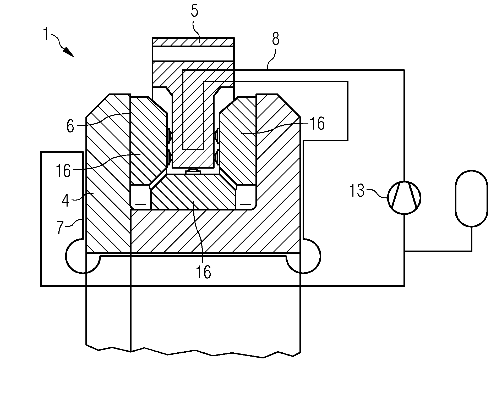
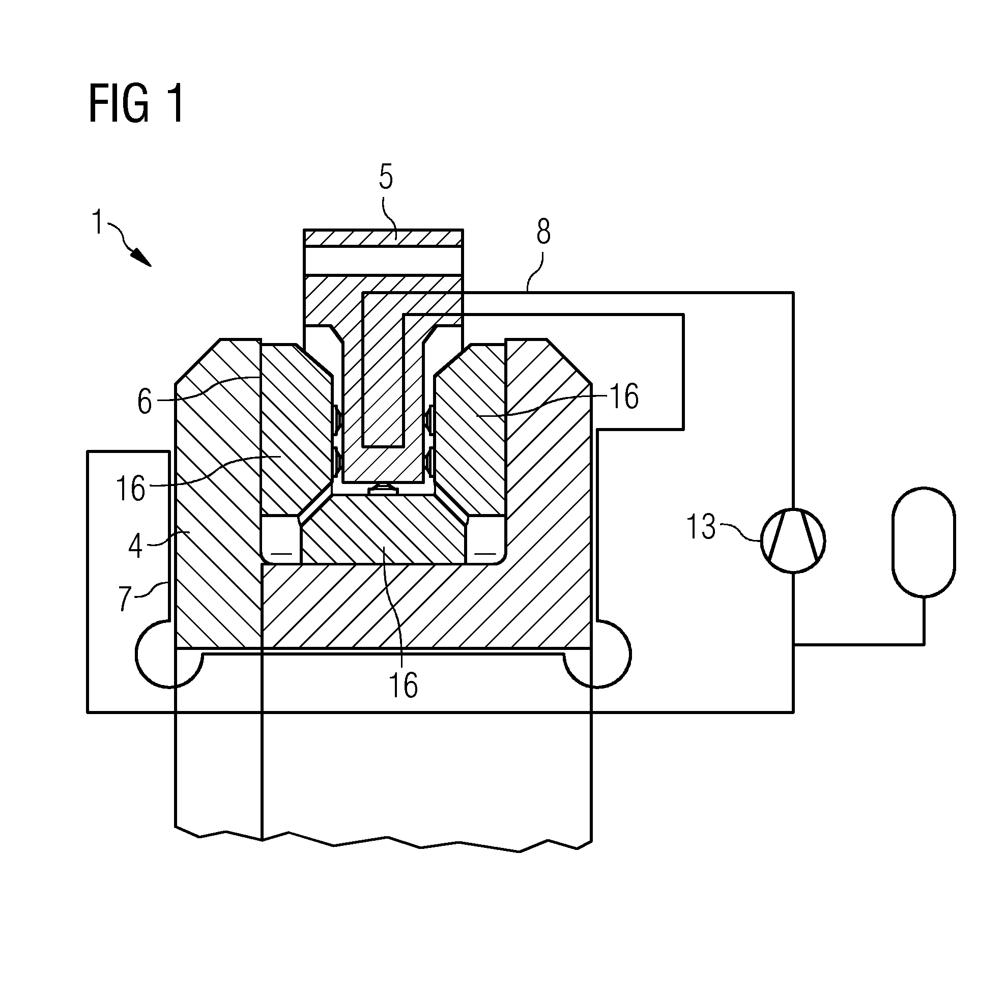
[0128]FIG. 1 shows a schematic view of the bearing arrangement.

[0129]FIG. 1 shows a bearing arrangement 1 comprising a bearing. The bearing comprises a first bearing shell 4 and a second bearing shell 5. Bearing pads 16 are attached to the second bearing shell 5. During operation of the bearing the bearing pads 16 slide along to the surface of the first bearing shell 4.

[0130]A certain clearance 6 is provided between the first bearing shell 4 and the second bearing shell 5. The clearance 6 has to be kept within a certain range, to avoid damages at the bearing or the wind turbine, for example.

[0131]A first circuit 7 is arranged at the first bearing shell 4. The first circuit 7 comprises a first fluid. The first circuit 7 is in thermal contact to the first bearing shell 4, so that thermal energy, heat for example, is transferred between the first bearing shell 4 and the first fluid. Thus the first bearing shell 4 is cooled or heated by the first fluid.

[0132]A second circuit 8 is arrang...

second embodiment

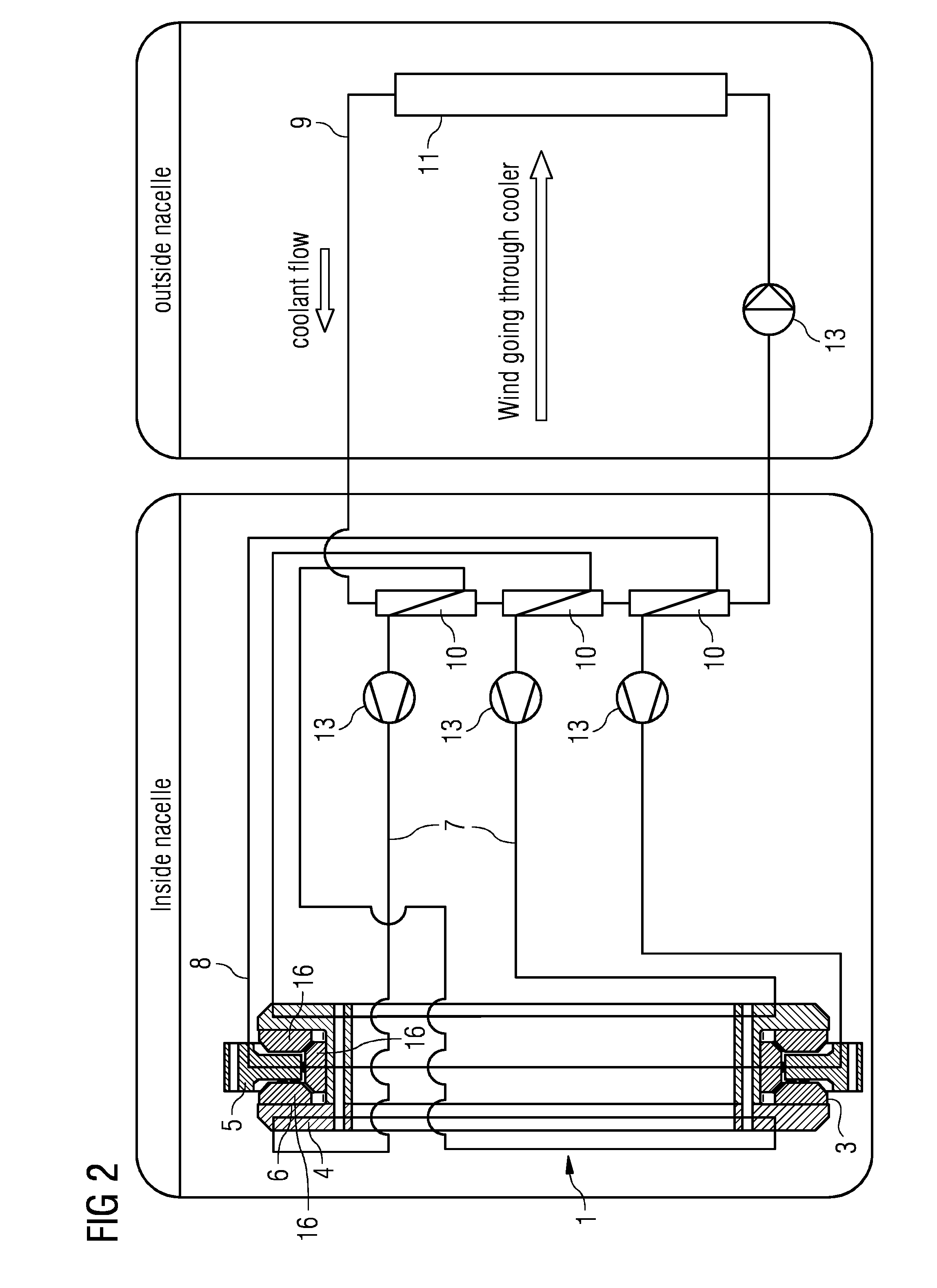
[0138]FIG. 2 shows the bearing arrangement.

[0139]FIG. 2 shows a bearing arrangement 1 with a bearing 3. The bearing 3 comprises a first bearing shell 4 and a second bearing shell 5. Bearing pads 16 are arranged between the first bearing shell 4 and the second bearing shell 5.

[0140]A first circuit 7 is arranged at the first bearing shell 4 to cool or heat the first bearing shell 4. In this embodiment the first circuit 7 is arranged in two loops along the first bearing shell 4.

[0141]A second circuit 8 is arranged at the second bearing shell 5, to cool or heat the second bearing shell 5.

[0142]The first circuit 7 and the second circuit 8 are connected via a heat exchanger 10.

[0143]The heat exchanger 10 is connected to a third circuit 9. The third circuit 9 comprises a third fluid. A pump 13 pumps the third fluid within the third circuit 9.

[0144]The first circuit 7 and the second circuit 8 are connected via the third circuit 9. Thus a difference in the temperature of the first fluid and ...


PUM


Abstract

An arrangement to control the clearance of a sliding bearing is disclosed. A sliding bearing arrangement, of a direct driven wind turbine, comprises a bearing. The bearing comprises a first bearing shell and a second bearing shell, whereby the first bearing shell and the second bearing shell are arranged rotatable in respect to each other. A certain predetermined clearance is present between the first bearing shell and the second bearing shell, while the bearing is in rotation. A first circuit comprises a first fluid, while the first circuit is in thermal contact with the first bearing shell. A second circuit comprises a second fluid, while the second circuit is in thermal contact with the second bearing shell. The first circuit and the second circuit are coupled in a way that a difference in the temperature between the first bearing shell and the second bearing shell is compensated via the first and the second fluid, thus the clearance is kept within a predetermined range.

Description

CROSS-REFERENCE TO RELATED APPLICATIONS[0001]This application claims priority to EP 13165508 filed on Apr. 26, 2013, the entire contents of which are hereby incorporated by reference.FIELD OF TECHNOLOGY[0002]The disclosed relates to an arrangement to control the clearance of a sliding bearing.BACKGROUND[0003]Bearings are built as rolling element bearings or as plain bearings. A plain bearing, or sliding bearing, is also known as a hydrodynamic bearing, a hydrostatic bearing or a hybrid bearing.[0004]The contact surface between a rolling element and a bearing shell is very small. In an arrangement, where higher loads act and higher moments have to be transferred over the bearing, rolling element bearings are not sufficient.[0005]In such arrangements, plain bearings are applied. Plain bearing or sliding bearings are capable to transfer higher loads than rolling element bearings.[0006]In a direct driven wind turbine rotor of the electrical generator is directly coupled with the rotor o...

Claims


Application Information

Patent Timeline
Patent Type & Authority Applications(United States)
IPC IPC(8): F03D11/00
CPCF03D11/0008F16C37/00F16C17/243F03D80/70F16C2360/31F16C41/02F16C17/10F16C32/0666F16C32/067F16C32/0696Y10S384/90Y02E10/72
Inventor PEDERSEN, BOTHOMSEN, KIM
Owner SIEMENS GAMESA RENEWABLE ENERGY AS
Why Eureka
Try Eureka