Control apparatus for internal combustion engine

Active Publication Date: 2014-11-06
TOYOTA JIDOSHA KK
View PDF9 Cites 25 Cited by
  • Summary
  • Abstract
  • Description
  • Claims
  • Application Information

AI Technical Summary

Benefits of technology

[0010]The present invention has been conceived to solve the above described problem, and an object of the present invention is to provide a control apparatus for an internal combustion engine that, in a case where the internal combustion engine includes a turbo-supercharger and a waste gate valve that opens and clos

Problems solved by technology

For this reason, in a highland area, in some cases it is difficult to perform adjustment of the aforementioned required intake air amount using the throttle valve while catalyst warm-up control is being executed.
However, retarding the ignition timing leads to a decrease in the torque of the internal combustion engine.
Accordingly, in a highland area, in a case where maintaining the idling speed is prioritized when it has become difficult to secure the required intake air amount using the throttle valve during ex

Method used


Image

  • Control apparatus for internal combustion engine
  • Control apparatus for internal combustion engine
  • Control apparatus for internal combustion engine

Examples


embodiment 1

Description of System Configuration

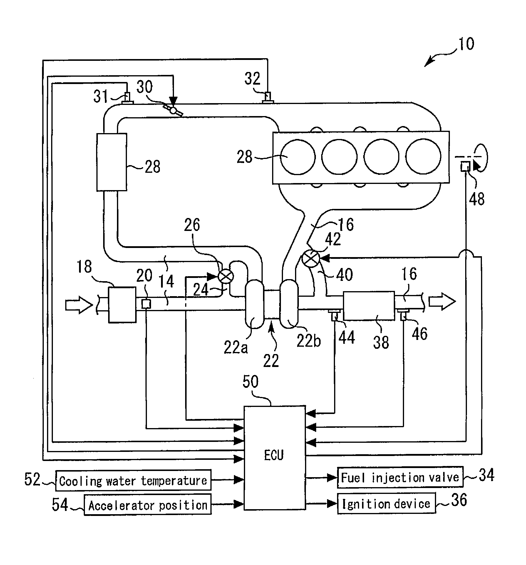
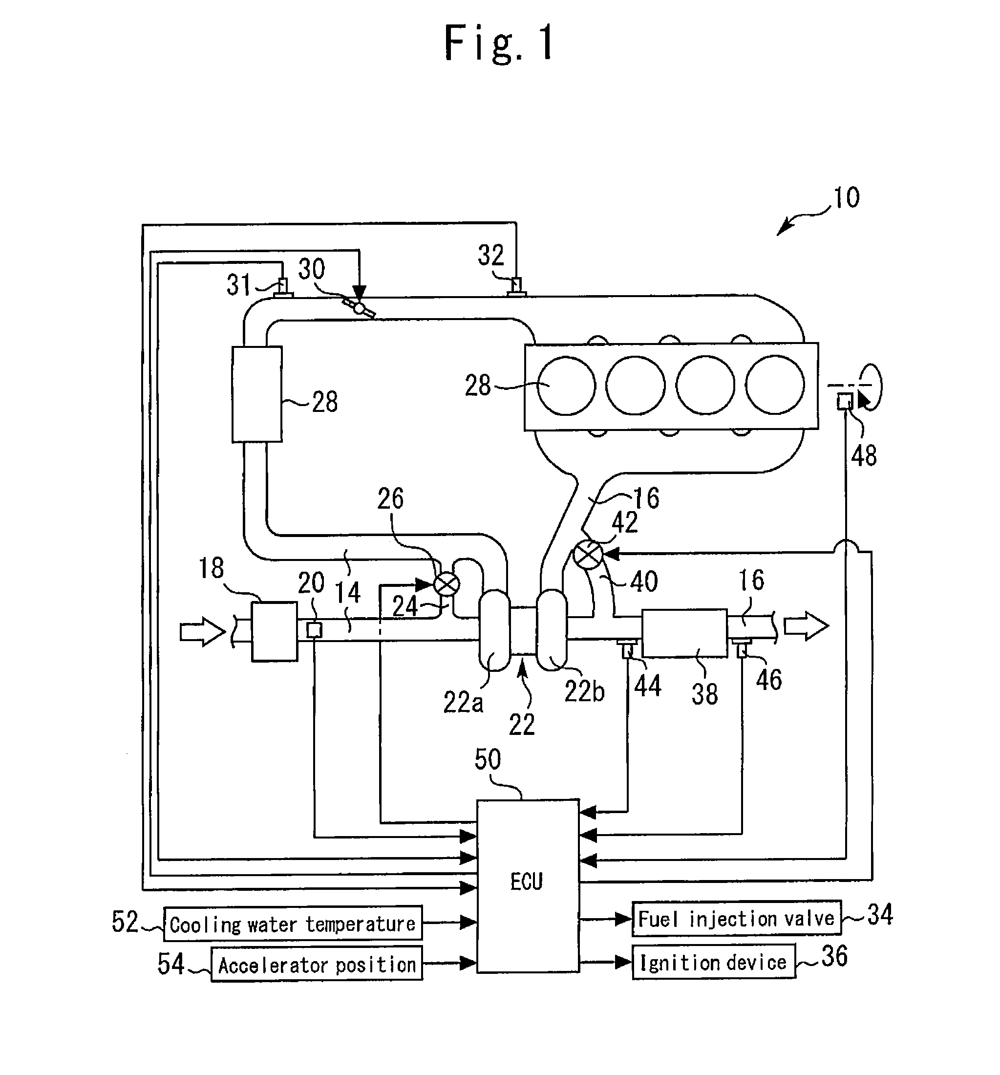
[0029]FIG. 1 is a schematic view for describing the system configuration of an internal combustion engine 10 according to Embodiment 1 of the present invention. A system of the present embodiment includes a spark ignition-type internal combustion engine (as one example, a gasoline engine) 10. A combustion chamber 12 is formed inside each cylinder of the internal combustion engine 10. An intake passage 14 and an exhaust passage 16 communicate with the combustion chamber 12.

[0030]An air cleaner 18 is installed in the vicinity of the inlet of the intake passage 14. An air flow meter 20 that outputs a signal in accordance with a flow rate of air that is drawn into the intake passage 14 is provided in the vicinity of the air cleaner 18 on the downstream side thereof. A compressor 22a of a turbo-supercharger 22 is arranged downstream of the air flow meter 20. The compressor 22a is integrally connected through a connecting shaft (not illustrated in the dr...

embodiment 2

[0072]Next, Embodiment 2 of the present invention will be described referring to FIG. 3.

[0073]The system of the present embodiment can be realized by using the hardware configuration illustrated in FIG. 1 and causing the ECU 50 to execute the routine shown in FIG. 3, described later, instead of the routine shown in FIG. 2.

[0074]In the above described Embodiment 1 a configuration is adopted in which, in a case where the sensitivity of control of the intake air amount by the throttle valve 30 is low when a catalyst warm-up request was issued, the intake air amount is adjusted by adjusting the degree of opening of the WGV 42 while the degree of opening of the throttle valve is kept constant. In contrast, according to the catalyst warm-up control of the present embodiment, a configuration is adopted in which, in a case where the sensitivity of control of the intake air amount by the throttle valve 30 is in a low state when a catalyst warm-up request was issued, the degree of opening of ...

embodiment 3

[0089]A system of the present embodiment can be realized by using the hardware configuration illustrated in FIG. 1 and causing the ECU 50 to execute the routine shown in FIG. 4, described later, instead of the routine shown in FIG. 2.

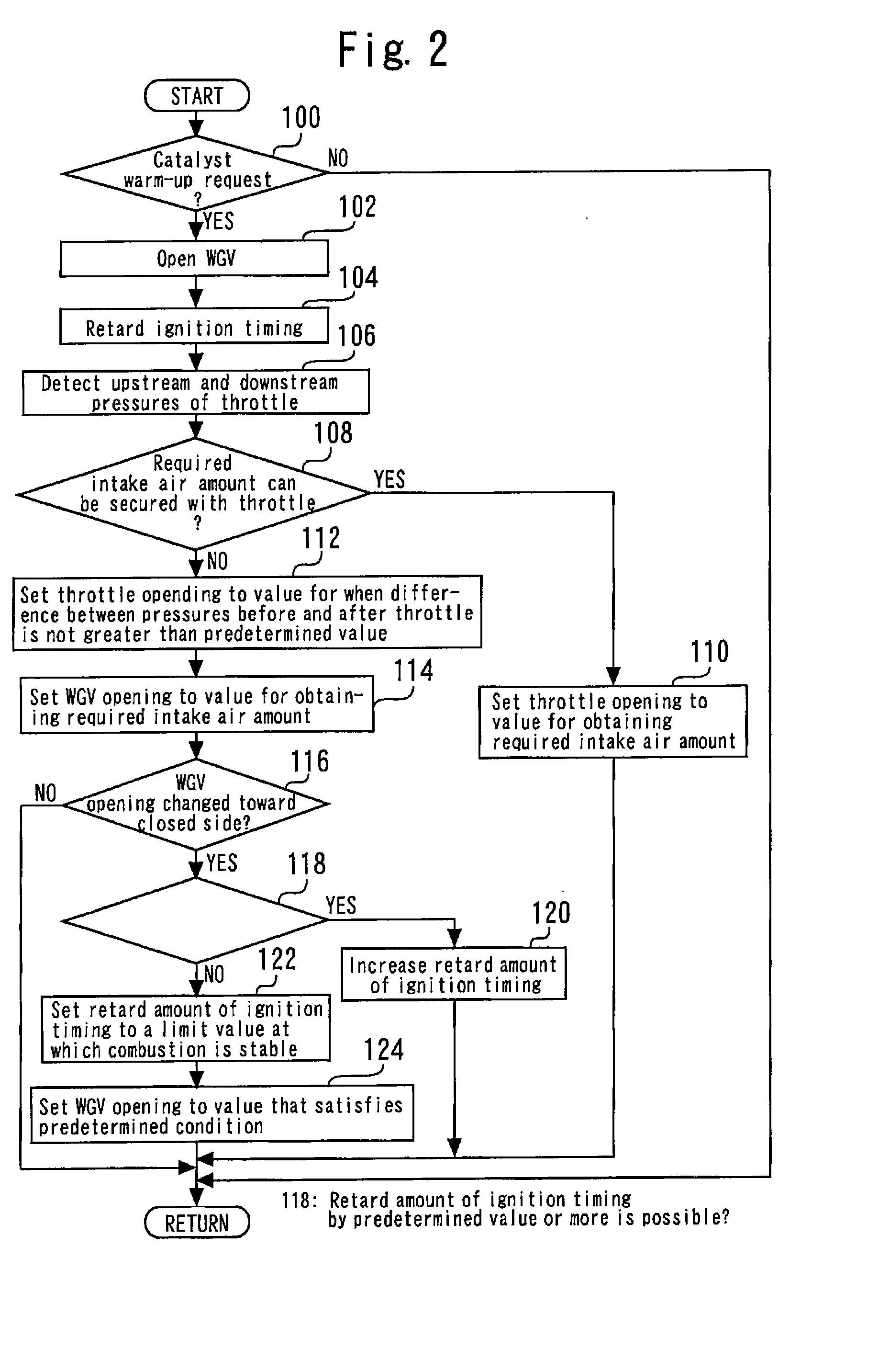
[0090]FIG. 4 is a flowchart illustrating a control routine that the ECU 50 executes in order to realize catalyst warm-up control according to Embodiment 3 of the present invention. In FIG. 4, steps that are the same as steps shown in FIGS. 2 and 3 according to Embodiments 1 and 2 are denoted by the same reference numerals, and a description of those steps is omitted or simplified.

[0091]As shown in FIG. 4, the processing of the present routine is processing that combines the routine shown in FIG. 2 and the routine shown in FIG. 3. That is, processing that is executed when the sensitivity of control of the intake air amount by the throttle valve 30 is in a high state when a catalyst warm-up request is issued is the same as in the routines shown in FIGS. 2...


PUM


Abstract

A control apparatus for an internal combustion engine of this invention includes: a turbo-supercharger; an exhaust gas purifying catalyst disposed in an exhaust passage on the downstream side of a turbine; and a WGV capable of opening and closing an exhaust bypass passage that bypasses the turbine. At the time of a catalyst warm-up request, catalyst warm-up control that opens the WGV and retards the ignition timing is executed. If the sensitivity of control of an intake air amount by a throttle valve is high, the intake air amount is controlled using the throttle valve during execution of the catalyst warm-up control. If the control sensitivity is low, the intake air amount is controlled using the WGV during execution of the catalyst warm-up control. When the WGV degree of opening is controlled toward a closed side during execution of the intake air amount control using the WGV, a retard amount of the ignition timing is increased.

Description

TECHNICAL FIELD[0001]The present invention relates to a control apparatus for an internal combustion engine, and more particularly to a control apparatus for a supercharged internal combustion engine that includes a turbo-supercharger and a waste gate valve that opens and closes an exhaust bypass passage that bypasses a turbine of the turbo-supercharger.BACKGROUND ART[0002]A control apparatus for an internal combustion engine which includes a turbo-supercharger and a waste gate valve that opens and closes an exhaust bypass passage that bypasses a turbine has already been disclosed in, for example, Patent Literature 1. According to the conventional control apparatus, a configuration is adopted so as to perform the following control to warm up an exhaust gas purifying catalyst that is disposed on the downstream side of the turbine after a cold startup. That is, when the internal combustion engine is in an idling state after a cold startup, the aforementioned control apparatus is confi...

Claims


Application Information

Patent Timeline
IPC IPC(8): F02D41/00F02P5/04F02B37/16F02B37/18F01N9/00
CPCF02D41/0007F02B37/186F02P5/045F02B37/16F01N9/00F01N2410/06F02B37/18F02D9/02F02D23/00F02D37/02F02D41/0002F02D41/024F02D41/068F02D41/086F02D2041/0017F02P5/1508Y02T10/12Y02T10/40
Inventor TSUNOOKA, TAKASHI
Owner TOYOTA JIDOSHA KK
Why Eureka
Try Eureka