
Optical sensing apparatus

a technology of optical sensing apparatus and optical sensor, which is applied in the direction of force measurement by measuring optical property variation, apparatus for force/torque/work measurement, instruments, etc., can solve the problems of inability to correct a change in a property measurement, unreliable, and significant drawbacks of optical systems, so as to facilitate the use of optical apparatus, minimise the effect of a change, and facilitate the effect of application

Active Publication Date: 2014-11-06
ARKWRIGHT TECH PTY LTD
View PDF3 Cites 10 Cited by
  • Summary
  • Abstract
  • Description
  • Claims
  • Application Information

AI Technical Summary

Benefits of technology

The patent describes an optical sensing apparatus that can be used in various applications, such as measuring blood pressure or monitoring forces in the body. The apparatus is designed in a narrow way to make it easy to use in different environments. The apparatus uses Bragg gratings, which can detect changes in temperature and pressure. By measuring these changes in both modes of optical responses, the apparatus can minimize the effect of temperature changes on the measurement results. The close proximity of the optical fibers also helps reduce temperature differences between the sensing regions, which makes the apparatus more suitable for in-vivo applications. Overall, the optical sensing apparatus provides a flexible and efficient tool for measuring pressure and temperature in various situations.

Problems solved by technology

However, such optical systems still have significant drawbacks.
For example, it is often not possible, or it is inconvenient and unreliable to correct a measurement of a change in a property, such as a pressure, for differential temperature change especially if a probe of the optical system has to be very narrow.

Method used


Image

  • Optical sensing apparatus
  • Optical sensing apparatus
  • Optical sensing apparatus

Examples


Embodiment Construction

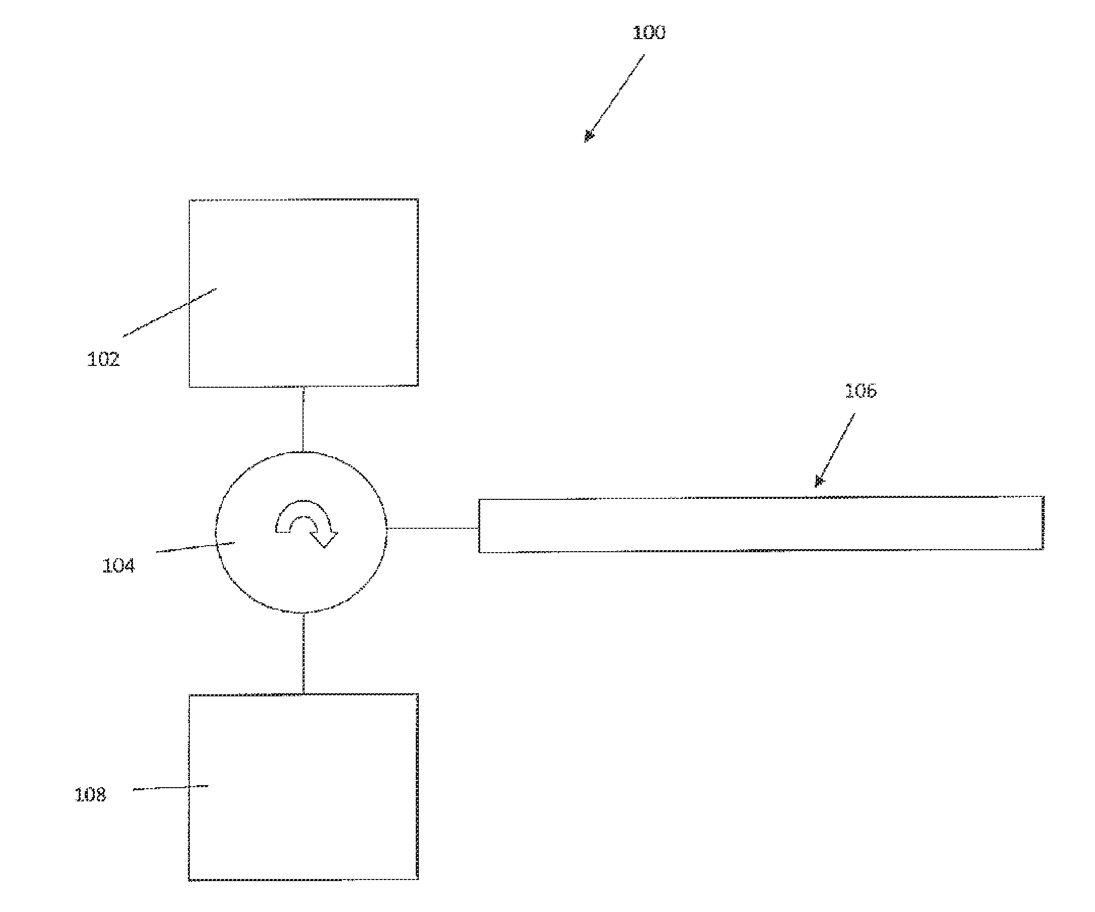
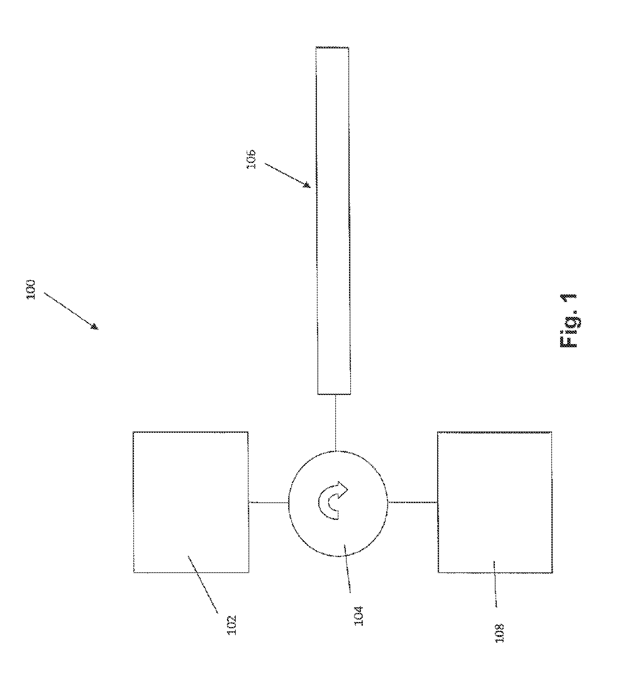
[0051]Referring initially to FIG. 1, a system for measuring a first property is now described. In the described embodiment the first property is a pressure. However, it is to be appreciated by a person skilled in the art that the apparatus may alternatively be arranged for sensing other properties such as a force that may for example be associated with a chemical or biochemical reaction initiated in the proximity of the system.

[0052]The system 100 comprises a light source 102 which in this embodiment is a broadband light source commonly referred to as a “white” light source even though the light that is emitted by the light source 102 may have any wavelength range. The light is directed via optical circulator 104 to an apparatus for pressure sensing 106. In a variation of this embodiment the circulator 104 may be replaced by an optical coupler, an optical splitter or an optical beam splitter. The system 100 further comprises an optical analyser 108 for analysing an optical response ...


PUM

PropertyMeasurementUnit
widthaaaaaaaaaa
widthaaaaaaaaaa
widthaaaaaaaaaa

Abstract

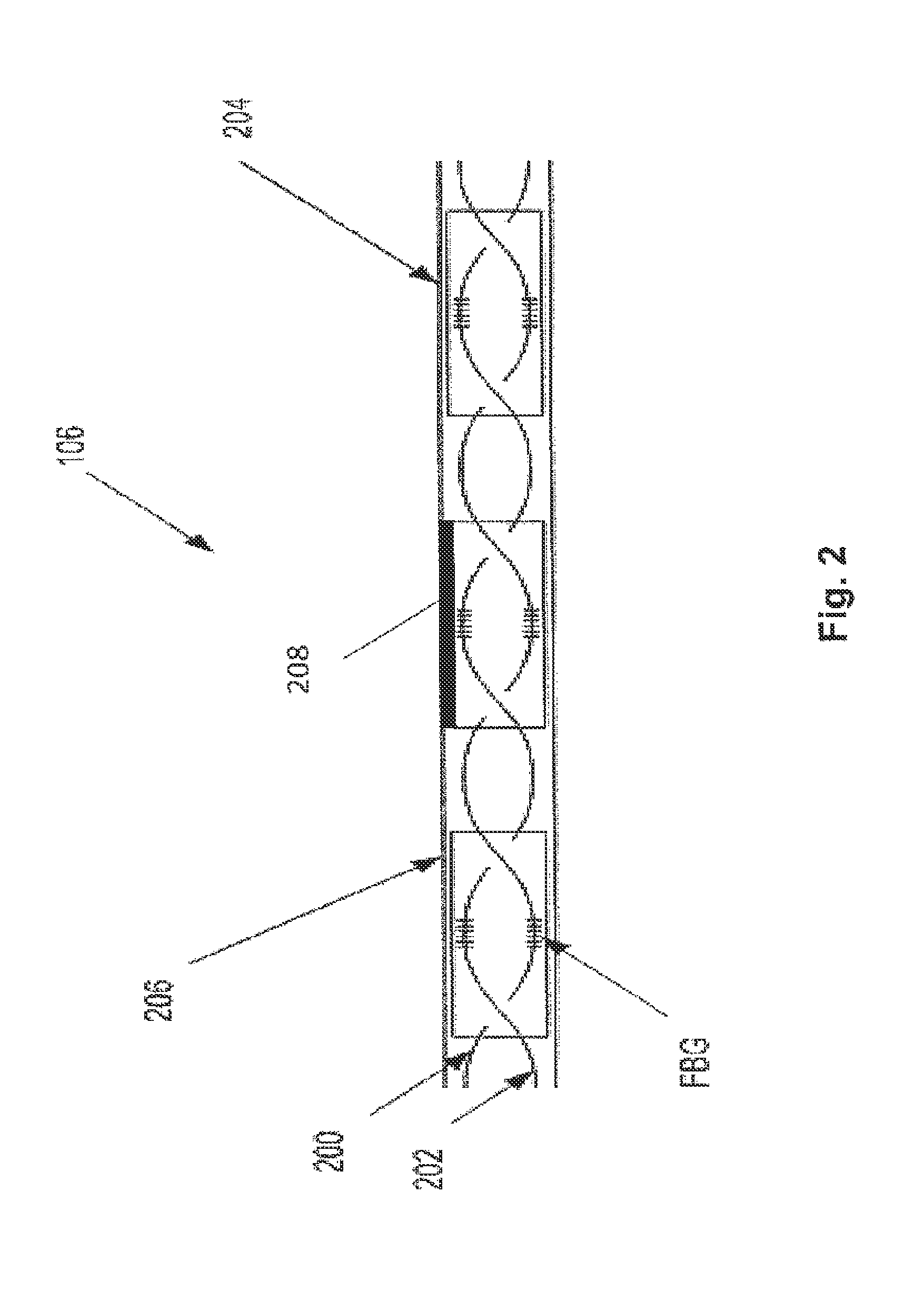
The present disclosure provides an optical sensing apparatus for measuring a change in a first property. The optical sensing apparatus comprises first and second optical fibre portions and a sensing region for exposing both the first and second optical fibre portions to a change in an applied force. The force is, or is related to, the first property and has a component that is transversal to the optical fibre portions. The apparatus further comprises a holder for holding the first and second optical fibre portions in the sensing region. The first and second optical fibre portions are arranged relative to each other such that the change in the force results in a first change of an optical property of the first optical fibre portion and in a second change of the optical property of the second optical fibre portion and wherein the first change differs from the second change.

Description

FIELD OF THE INVENTION[0001]The present invention broadly relates to an optical sensing apparatus and relates particularly, though not exclusively, to an optical sensing apparatus for measuring a change in an applied pressure or force.BACKGROUND OF THE INVENTION[0002]The ability to sense changes in properties within narrow regions, such as narrow body lumens, is of increasing interest for research and diagnostic or analytical purposes. For example, the human heart pumps blood through the body and the measurement of blood pressure within blood vessels is of interest for characterising a circulatory system of a patient. Another example relates to diagnostic needs to measure a distribution of pressures exerted by muscles around the alimentary canal, which moves food from the mouth into the stomach. Further, there are many examples in other fields of technology that require measurements of properties in narrow areas, such as in water or gas pipes.[0003]Optical devices for monitoring suc...

Claims


Application Information

Patent Timeline
Patent Type & Authority Applications(United States)
IPC IPC(8): G01L1/24
CPCG01L1/246G01D5/35316G01D5/35374G01K11/3206
Inventor ARKWRIGHT, JOHN WILLIAMMAUNDER, ADAM SIMONWANG, HSIAO-CHUAN
Owner ARKWRIGHT TECH PTY LTD
Learn More