
Methods of Hydraulically Fracturing and Recovering Hydrocarbons

a technology of hydraulic fracturing and hydrocarbon recovery, applied in the field of synthetic proppants, can solve the problems of increasing and unfulfilled needs, not progressing at a sufficient rate and pace, and in particular proppants and fracturing fluids, so as to improve the conductivity of wells, increase the recovery of hydrocarbons, and enhance the effect of well conductivity

Active Publication Date: 2014-11-06
MELIOR INNOVATIONS
View PDF7 Cites 23 Cited by
  • Summary
  • Abstract
  • Description
  • Claims
  • Application Information

AI Technical Summary

Benefits of technology

[0044]Thus, there is provided a method of enhancing conductivity of a well to increase the recovery of hydrocarbons from a subterranean hydrocarbon reservoir associated with the well, the method including: positioning a polysiloxane derived ceramic proppant in a fluid channel in a subterranean reservoir comprising hydrocarbons, whereby the proppant is in fluid association with the hydrocarbons; and, flowing the hydrocarbons over the polysiloxane derived ceramic proppant; and, recovering the hydrocarbons that have flowed over the proppant.
[0049]Moreover, there is provided a method of enhancing conductivity of a well to increase the recovery of hydrocarbons from a subterranean hydrocarbon reservoir associated with the well, the method including: positioning a synthetic proppant in a fluid channel in a subterranean reservoir comprising hydrocarbons, whereby the proppant is in fluid association with the hydrocarbons; the proppant having an apparent specific gravity of less than about 2 and a crush test of less than about 1% fines generated at 10,000 psi., flowing the hydrocarbons over the polysiloxane derived ceramic proppant; and, recovering the hydrocarbons that have flowed over the proppant.
[0051]Further there is provided a method of enhancing conductivity of a well to increase the recovery of hydrocarbons from a subterranean hydrocarbon reservoir associated with the well, the method including: positioning a synthetic proppant in a fluid channel in a subterranean reservoir comprising hydrocarbons, whereby the proppant is in fluid association with the hydrocarbons; the proppant having an apparent specific gravity of less than about 2.5 and a crush test of less than about 1% fines generated at 15,000 psi., flowing the hydrocarbons over the polysiloxane derived ceramic proppant; and, recovering the hydrocarbons that have flowed over the proppant.
[0052]Furthermore, there is provided a method of enhancing conductivity of a well to increase the recovery of hydrocarbons from a subterranean hydrocarbon reservoir associated with the well, including: positioning a ceramic proppant in a fluid channel in a subterranean reservoir comprising hydrocarbons, whereby the proppant is in fluid association with the hydrocarbons; the proppant comprises silicon, oxygen and carbon; and, flowing the hydrocarbons over the proppant; and, recovering the hydrocarbons that have flowed over the proppant.
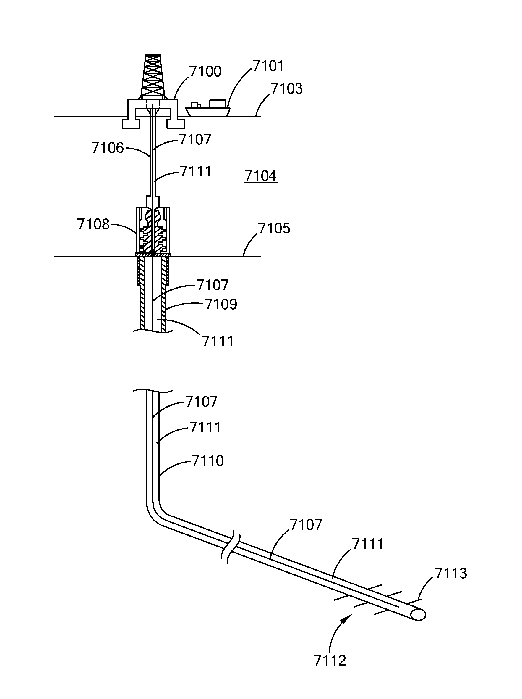
[0058]Still additionally there is provide a method of enhancing conductivity of a well to increase the recovery of hydrocarbons from a subterranean hydrocarbon reservoir associated with the well, the method including: locating a plurality of polysiloxane derived ceramic proppants in flow channels in a subterranean formation comprising a reservoir of hydrocarbons, whereby the proppants are in contact with the formation and the hydrocarbons; and, a well connecting a surface of the earth to the formation; moving the hydrocarbons from the formation through the proppant containing flow channels and into the well; and moving the hydrocarbons to the surface.

Problems solved by technology

Hydraulic fracturing technology, and in particular proppants and fracturing fluids, have not advanced at a sufficient rate and pace, to keep up with the evolution and advances in hydrocarbon exploration and production.
Thus, there exists a long felt, increasing and unfulfilled need for, among other things, a proppant material having predetermined characteristics to enhance hydraulic fracturing operations and the recovery of natural resources, such as oil and natural gas, from wells.

Method used


Image

  • Methods of Hydraulically Fracturing and Recovering Hydrocarbons
  • Methods of Hydraulically Fracturing and Recovering Hydrocarbons
  • Methods of Hydraulically Fracturing and Recovering Hydrocarbons

Examples


example 1

[0280]Using a tower forming and cure system, a polysilocarb batch having 75% MH, 15% TV, 10% VT and 1% catalyst (10 ppm platinum and 0.5% Luprox 231 peroxide) is formed from a sonic nozzle having an internal diameter of 0.180 inches into droplets that fall from the nozzle into and through an 8 foot curing tower. The temperature at the top of the tower is from 495-505° C. the temperature at the bottom of the tower is 650° C. There are no discrete temperature zones in the tower. Airflow up the tower is by convection. A collection pan at the bottom of the tower is maintained at 110° C. The forming and curing are done in air. The preform proppants are removed from the pan and post (hard) cured at 200° C. in air for 2 hours. The hard cured preform proppants are pyrolized at 1000° C. in an argon atmosphere for 2 hours. The cure yield is from 99% to 101%. The char yield is 86%.

example 2

[0281]Using a tower forming and cure system, a polysilocarb batch having 70% MH, 20% TV, 10% VT and 1% catalyst (10 ppm platinum and 0.5% Luprox 231 peroxide) is formed from a sonic nozzle having an internal diameter of 0.180 inches into droplets that fall from the nozzle into and through an 8 foot curing tower. The temperature at the top of the tower is from 495-505° C. the temperature at the bottom of the tower is 650° C. There are no discrete temperature zones in the tower. Airflow up the tower is by convection. A collection pan at the bottom of the tower is maintained at 110° C. The forming and curing are done in air. The preform proppants are removed from the pan and post (hard) cured at 200° C. in air for 2 hours. The hard cured preform proppants are pyrolized at 1000° C. in an argon atmosphere for 2 hours. The cure yield is from 99% to 101%. The char yield is 86%.

example 2a

[0282]Turning to FIG. 66, there is provided a chart comparing the strength and density of an embodiment of the proppant of Example 2 with prior art proppants.


PUM


Abstract

There is provided synthetic proppants, and in particular polysilocarb derived ceramic proppants. There is further provided hydraulic fracturing treatments utilizing these proppants, and methods of enhance hydrocarbon recovery.

Description

[0001]This application: (i) claims under 35 U.S.C. §119(e)(1) the benefit of the filing date of Jul. 4, 2013 of U.S. provisional application Ser. No. 61 / 843,014; (ii) claims under 35 U.S.C. §119(e)(1) the benefit of the filing date of Feb. 28, 2014 of U.S. provisional application Ser. No. 61 / 946,598; (iii) is a continuation-in-part of U.S. patent application Ser. No. 14 / 268,150 filed May 2, 2014, which claims, under 35 U.S.C. §119(e)(1), the benefit of the filing date of May 2, 2013 of U.S. provisional application Ser. No. 61 / 818,906 and the benefit of the filing date of May 3, 2013 of U.S. provisional application Ser. No. 61 / 818,981; and, (iv) is a continuation-in-part of U.S. patent application Ser. No. 14 / 212,896 filed Mar. 14, 2014, which claims under 35 U.S.C. §119(e)(1) the benefit of the filing date of Mar. 15, 2013 of U.S. provisional application Ser. No. 61 / 788,632, the entire disclosures of each of which are incorporated herein by reference.BACKGROUND OF THE INVENTION[0002...

Claims


Application Information

Patent Timeline
Patent Type & Authority Applications(United States)
IPC IPC(8): C09K8/588E21B43/267
CPCC09K8/588E21B43/267C08G77/12C08G77/20C08G77/50C08L83/04C04B33/1352C04B35/5603C04B35/571C04B2235/3217C04B2235/3418C04B2235/5436C04B2235/5445C04B35/6269C04B2235/3463C04B2235/3826C04B2235/5427C04B2235/5481C04B2235/77C04B2235/94Y02P40/60C08L83/00E21B43/01C09K2208/00
Inventor MOELLER, TIMOTHYSHERWOOD, WALTERLAND, MARKELY, JOHNDYK, THOMASHOPKINS, ANDREW
Owner MELIOR INNOVATIONS
Learn More