

Insulated electric cable
- Summary
- Abstract
- Description
- Claims
- Application Information
AI Technical Summary
Benefits of technology
Problems solved by technology
Method used
Image

Examples
first embodiment
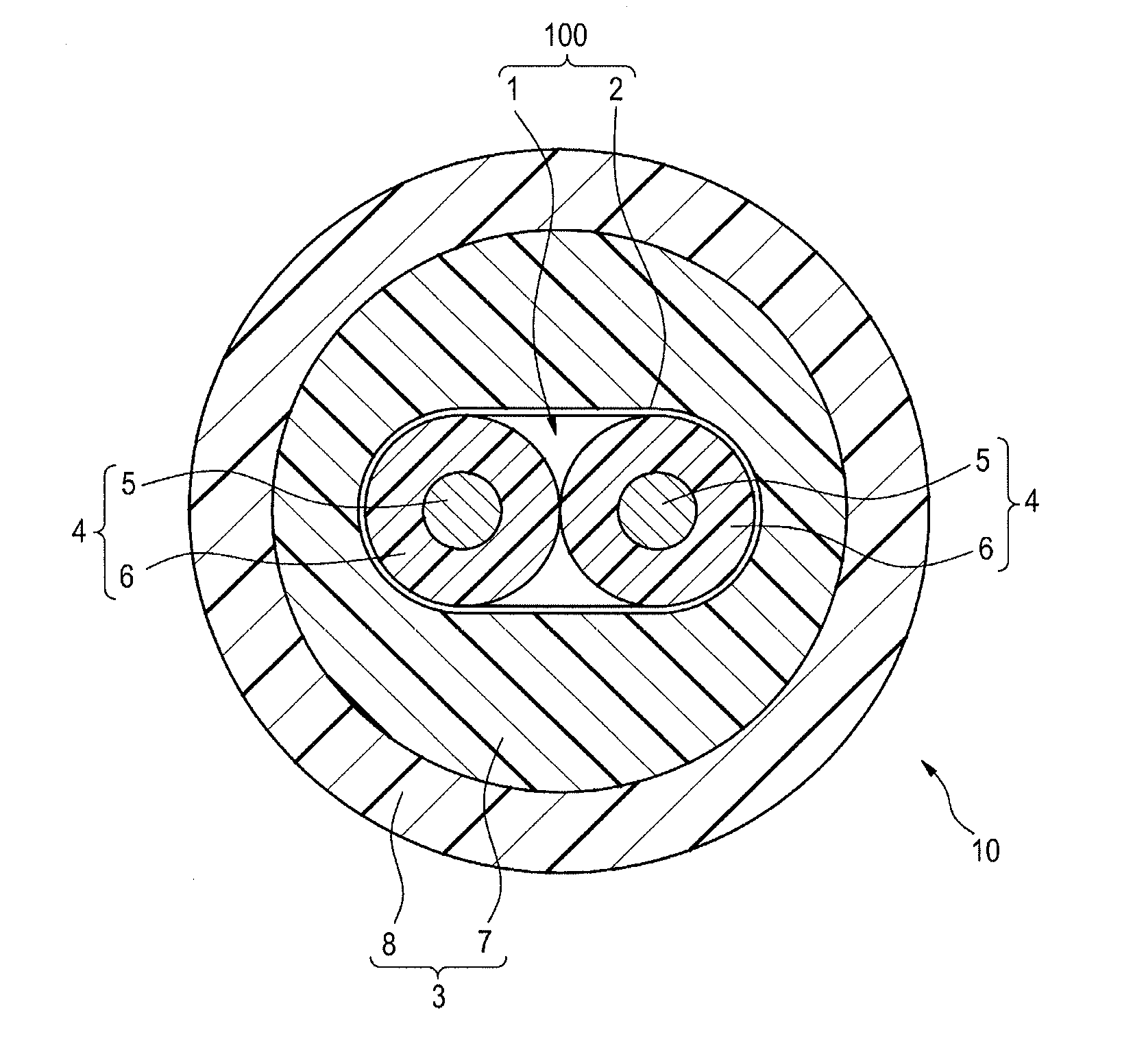
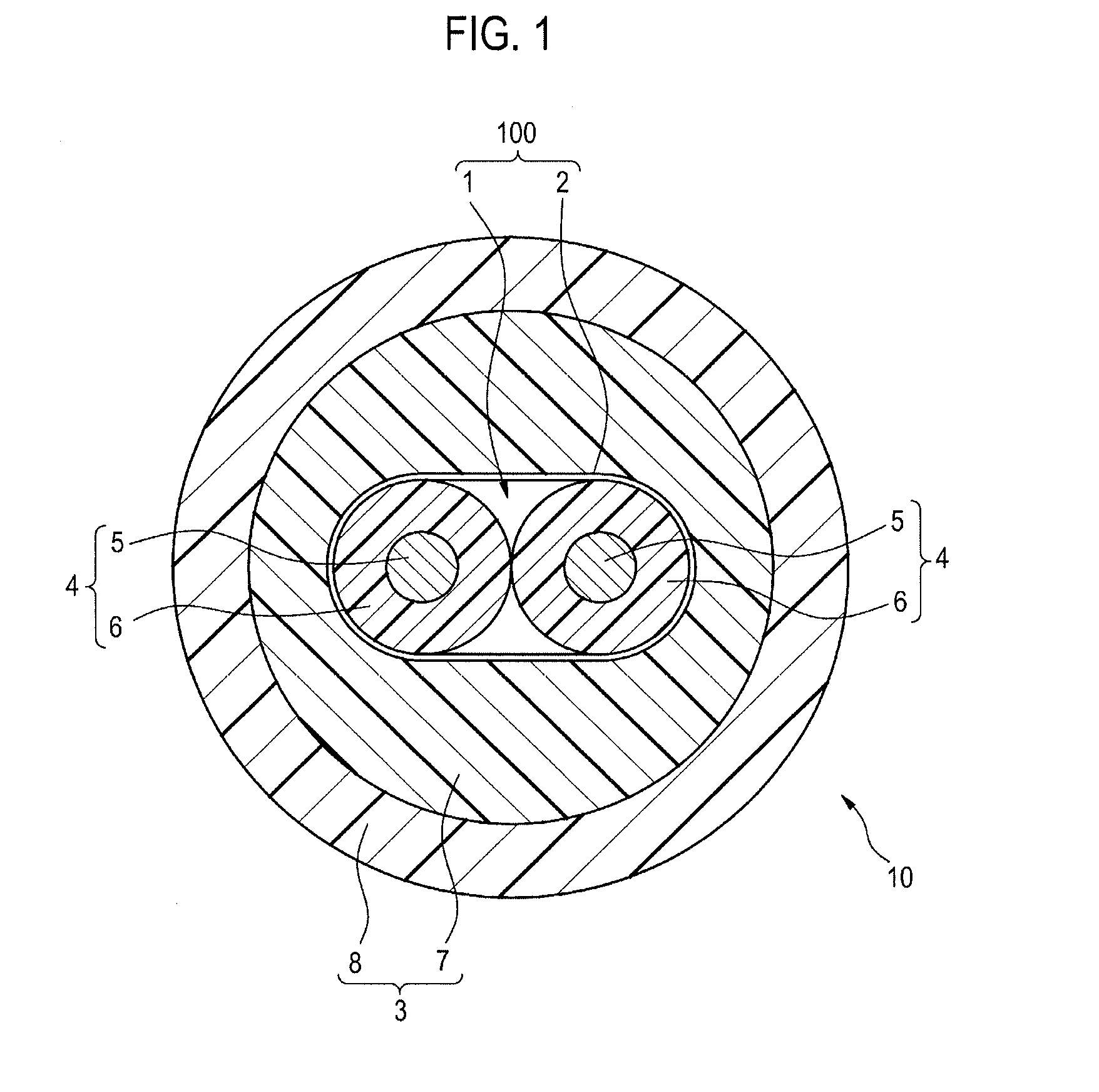
[0033]FIG. 1 is a sectional view showing a configuration of an insulated electric cable 10 according to a first embodiment of the invention. The insulated electric cable 10 is used in, for example, an electro mechanical parking brake (EPB) mounted in a vehicle, and can be used as a cable for sending an electrical signal to a motor for driving a brake caliper.
[0034]As shown in FIG. 1, the insulated electric cable 10 includes a core member 1, a paper tape 2 (one example of a tape member) wrapped around the core member 1, and a sheath 3 covering an outer periphery of the paper tape 2 wrapped around the core member 1. An outside diameter of the insulated electric cable 10 of the present example is set so as to be in the range of 6 to 12 mm, preferably, the range of 8.3 to 10.3 mm.
[0035]The core member 1 is formed by mutually stranding two first core wires 4 (one example of a core wire) respectively having the same diameter mutually. Each of the two first core wires 4 is constructed of a...
second embodiment
[0049]Next, a second embodiment of the invention will be described with reference to FIG. 3. In addition, description is omitted by assigning the same numerals to the same components as those of the first embodiment. FIG. 3 shows a cross section of an insulated electric cable 30 according to the second embodiment. The insulated electric cable 30 of the present example can be used to send an electrical signal for controlling operation of an antilock brake system (ABS) in addition to use for sending an electrical signal of an electro mechanical parking brake.
[0050]As shown in FIG. 3, the insulated electric cable 30 of the present example differs from that of the first embodiment in that a core member 1A has a subunit 31 for sending a signal for ABS in addition to two first core wires 4.
[0051]The subunit 31 is formed by mutually stranding two second core wires 32 (one example of a core wire) respectively having a diameter smaller than a diameter of the first core wire 4 and the same di...
example 1
[0059]As an insulated electric cable (for EPB) for test, the cable with each part having the following configuration was manufactured. As a material of a conductor constructing a first core wire, a copper alloy wire (a stranded wire formed by stranding 7 stranded wires formed by stranding 52 wires with an outside diameter of 0.08 m) was used, and a cross-sectional area (cross-sectional area of the total of wires) of the conductor was set at 1.8 mm2, and an outside diameter of the conductor was set at 2.0 mm. Also, as a material of an insulating layer formed on the periphery of the conductor, flame-retardant cross-linked polyethylene was used, and a thickness of the insulating layer was set at 0.4 mm, and an outside diameter of the insulating layer was set at 2.8 mm. Also, the number of core wires (first core wires) constructing a core member was set at 2, and a strand diameter (outside diameter in a stranded state) was set at 5.6 mm. Also, as a configuration of a tape member, a pape...
PUM
 Abstract
Description
Claims
Application Information