Rotating cutting elements for pdc bits

a technology of rotary drill bits and cutting elements, which is applied in the field of cutting elements, can solve the problems of drill bit failure, cutter failure, and bit and pdc cutter being subjected to substantial abrasion forces during drilling operations,

a technology of rotary drill bits and cutting elements, which is applied in the field of cutting elements, can solve the problems of drill bit failure, cutter failure, and bit and pdc cutter being subjected to substantial abrasion forces during drilling operations,

US20140326515A1Inactive Publication Date: 2014-11-06SMITH INT INC

Image

  • Rotating cutting elements for pdc bits
  • Rotating cutting elements for pdc bits
  • Rotating cutting elements for pdc bits

Examples


Embodiment Construction

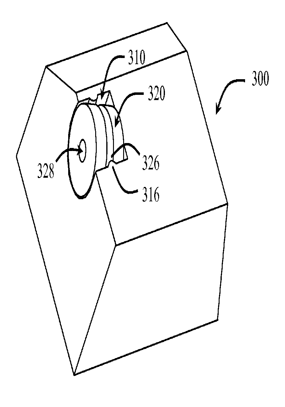
[0046]In one aspect, embodiments disclosed herein relate to rolling cutters and methods of retaining such rolling cutters on a drill bit or other cutting tools. In some embodiments, rolling cutters may be retained on a fixed cutter drill bit by a retention pin or a WC sleeve and the side surface of a rolling cutter pocket, thus allowing the entire cutting face of a rolling cutter to be exposed. According to other embodiments, rolling cutters may be retained on a fixed cutter drill bit by only the side surface of a rolling cutter pocket.

[0047]Generally, cutting elements described herein allow at least one surface or portion of the cutting element to rotate as the cutting elements contact a formation. As the cutting element contacts the formation, the cutting action may allow portion of the cutting element to rotate around a cutting element rotational axis extending through the cutting element. Rotation of the cutting structure may allow for a cutting surface to cut the formation usin...


PUM

PropertyMeasurementUnit
temperatureaaaaaaaaaa
arc angleaaaaaaaaaa
arc angleaaaaaaaaaa

Abstract

A drill bit has a bit body, a plurality of blades extending radially from the bit body, at least one rolling cutter pocket disposed on the plurality of blades, and at least one rolling cutter, wherein each rolling cutter is disposed in one of the rolling cutter pockets, and wherein a side surface of the rolling cutter pocket and an outer circumferential surface of the rolling cutter have at least one mating lip and channel formed therein. Further, the rolling cutter may include a cavity extending at least partially along a rotational axis through the rolling cutter, from a bottom surface of the rolling cutter, and a retention pin disposed within the cavity.

Description

BACKGROUND[0001]1. Technical Field[0002]Embodiments disclosed herein relate generally to cutting elements for drill bits or other tools incorporating the same. More specifically, embodiments disclosed herein relate generally to rotatable cutting elements for rotary drill bits.[0003]2. Background Art[0004]Drill bits used to drill wellbores through earth formations generally are made within one of two broad categories of bit structures. Depending on the application / formation to be drilled, the appropriate type of drill bit may be selected based on the cutting action type for the bit and its appropriateness for use in the particular formation. Drill bits in the first category are generally known as “roller cone” bits, which include a bit body having one or more roller cones rotatably mounted to the bit body. The bit body is typically formed from steel or another high strength material. The roller cones are also typically formed from steel or other high strength material and include a p...

Claims


Application Information

Patent Timeline
06 Nov 2014
Publication
US20140326515A1
IPC
E21B10/08; B23P15/28
CPC
B23P15/28; E21B10/08; E21B10/46; E21B10/43; E21B10/573; E21B10/633
Inventors
SHI, JIBIN; ZHANG, YOUHE