
Determination of angle of incidence

a technology of incidence angle and angle, applied in the direction of indication/recording movement, weapons, instruments, etc., can solve the problems of navigation system does not give a complete or correct position determination, no or limited information, etc., and achieve the effect of simplifying the gnc system

Active Publication Date: 2014-11-06
BAE SYST BOFORS
View PDF1 Cites 5 Cited by
  • Summary
  • Abstract
  • Description
  • Claims
  • Application Information

AI Technical Summary

Benefits of technology

The proposed method and system for determining the angle of incidence of a projectile through a wind tunnel or through calculations based on moments measured from control surfaces or fins are described in detail. This angle of incidence can be used along with information from a roll gyro, pitch and yaw angles, and a GPS receiver to create a simplified guidance system. Compared to traditional systems, the proposed method requires only one gyro instead of three gyros and three accelerometers. The technical effect is a more efficient and simplified guidance system for projectiles.

Problems solved by technology

One problem with the method according to US 2010 / 0176238 A1 is that no or limited information is obtained concerning the angle of incidence, which means that the navigation system does not give a complete or correct position determination.
One problem with the method according to U.S. Pat. No. 6,779,752 B1 is that no or limited information is obtained concerning the roll angle, which means that the navigation system does not give a complete or correct position determination.
One problem with the method according to U.S. Pat. No. 5,775,636 is that no or limited information is obtained concerning the roll angle, the angle of incidence or the yaw angle, which means that the navigation system does not give a complete or correct position determination.
One problem with the method according to U.S. Pat. No. 7,163,176 B1 is that no or limited information is obtained concerning the angle of incidence, which means that the navigation system does not give a complete or correct position determination.
A problem with currently existing solutions according to the above-stated documents is thus that no or limited information is obtained concerning the angle of incidence, which means that the navigation system does not give a complete or correct position determination.

Method used


Image

  • Determination of angle of incidence
  • Determination of angle of incidence

Examples


Embodiment Construction

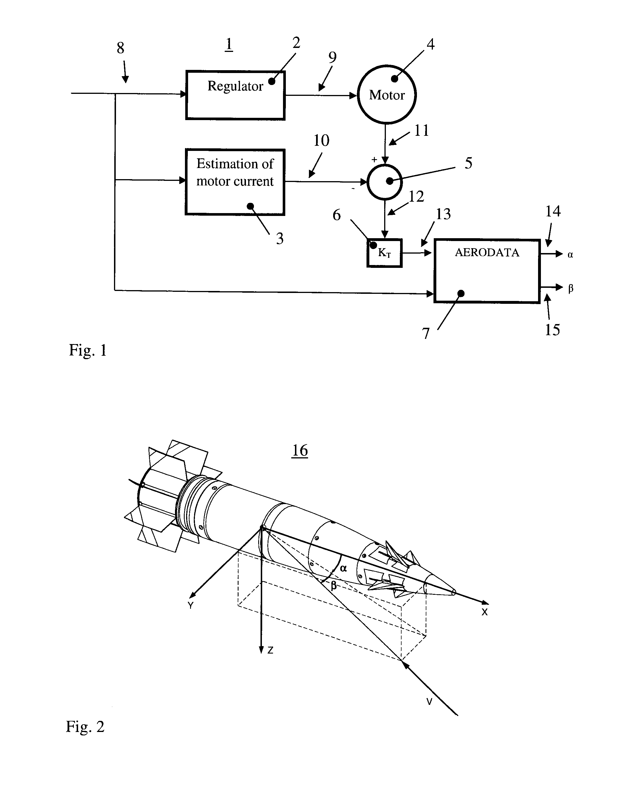
[0036]In FIG. 1 is shown a block diagram illustrating a method for determining and calculating angle of incidence 1, in which a regulator 2, on the basis of a desired reference signal 8, controls a motor 4. The reference signal 8 is constituted by the set point for the motor. The motor can also be termed a servo or actuator. The reference signal 8 is generated from the control system of the projectile. The motor 4 can be a linear motor, but is preferably a motor with rotating axle. The measured motor current 11 is compared with motor current 10 which is estimated on the basis of the signal and which emanates from the estimation of motor current 3 by the calculating block. The result of the difference between measured motor current 11 and estimated motor current 10 results in a current difference 12, which becomes input data to a model of the current / force function 6 of the motor. An output signal 13 from the current / force function of the motor is a signal which corresponds to the di...


PUM


Abstract

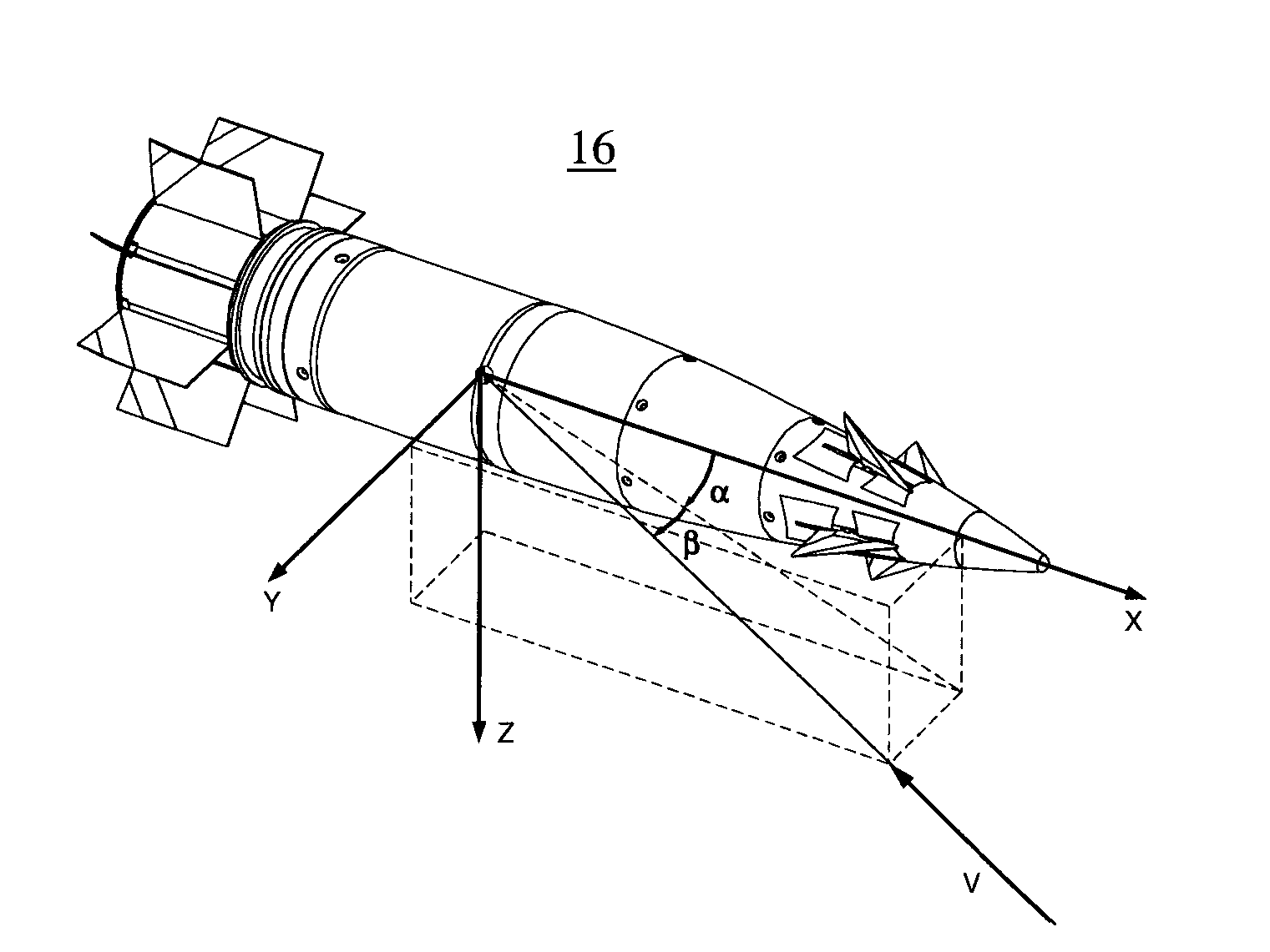
The invention relates to a method for determining angle of incidence for a projectile in the path of the projectile from launcher to target, which projectile is guidable and substantially or partially roll-stable and comprises a control system and at least two actuators with associated control members, in which the following steps are included: determination of applied force for pitch control by evaluation of the moment upon the actuators of the projectile, determination of applied force for yaw control by evaluation of the moment upon the actuators of the projectile, calculation of the pitch component α of the angle of incidence and of the yaw component β of the angle of incidence, based on comparison between the evaluated moments and reference data for moments. The invention also relates to a GNC system.

Description

TECHNICAL FIELD[0001]The present invention relates to a method for determining angle of incidence for a projectile in the path of the projectile from launcher to target, which projectile is guidable and substantially or partially roll-stable and comprises a control system and at least two actuators with associated control members. The invention also relates to a GNC system for a guidable projectile, which projectile is substantially or partially roll-stable and comprises a control system and at least two actuators with associated control members.BACKGROUND TO THE INVENTION, PROBLEM DEFINITION AND PRIOR ART[0002]Guidable projectiles use different forms of systems or devices for measuring and / or calculating their current position, attitude and velocity, as well as systems or devices for guiding the projectile. A collective name for these systems is GNC systems, in which GNC stands for Guidance, Navigation and Control. Knowledge of current position, with maximum possible accuracy, is i...

Claims


Application Information

Patent Timeline
Patent Type & Authority Applications(United States)
IPC IPC(8): F42B10/62
CPCF42B10/62F42B10/64F42B10/60F42B15/01G01P13/025G05D1/49
Inventor LARSSON, MATS
Owner BAE SYST BOFORS
Learn More