
Multifunctional Sky Camera System for Total Sky Imaging and Spectral Radiance Measurement

a camera system and sky camera technology, applied in the field of total sky imaging techniques, can solve the problems of pixel saturation and blooming, excessive electron overflow to neighboring pixels, and large amount of sky imaging,

Inactive Publication Date: 2014-11-06
IBM CORP
View PDF9 Cites 7 Cited by
  • Summary
  • Abstract
  • Description
  • Claims
  • Application Information

AI Technical Summary

Problems solved by technology

The contrast required by sky imaging (1:1,000,000), however, far exceeds the capability of currently available digital imaging sensors (typically 1:1,000 or less dynamic range).
On the other hand, the high intensity direct sun light without significant attenuation impinging on imaging sensors causes pixel saturation and blooming, i.e., accumulation of photoelectrons exceeds the designed linear-response and charge-holding capabilities of sensor pixels (saturation), which causes the excessive electrons to overflow to its neighboring pixels (blooming).
Blooming causes artifacts in sensor output which include large image area around sun being smeared out, streak patterns on image, and erroneous pixel values.
In extreme cases, even complete failure of a sensor can result from blooming due to breakdown of the preamplication stage.
The usage of mechanical sun blockers increases the cost of sky cameras and decreases their reliability in harsh field environments.
Moreover, information on the sun and the part of the sky adjacent to the sun (typically around a 10 degree field of view), which is most important for solar power forecast, is lost because of the blocking.
Moreover, because the sun is blocked, such sky camera systems can only image the sky around the sun and cannot measure the solar radiation.
This significantly increases the overall system complexity and cost.

Method used


Image

  • Multifunctional Sky Camera System for Total Sky Imaging and Spectral Radiance Measurement
  • Multifunctional Sky Camera System for Total Sky Imaging and Spectral Radiance Measurement
  • Multifunctional Sky Camera System for Total Sky Imaging and Spectral Radiance Measurement

Examples


Embodiment Construction

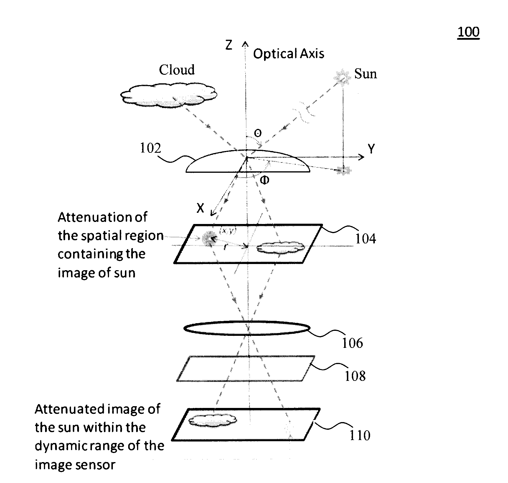
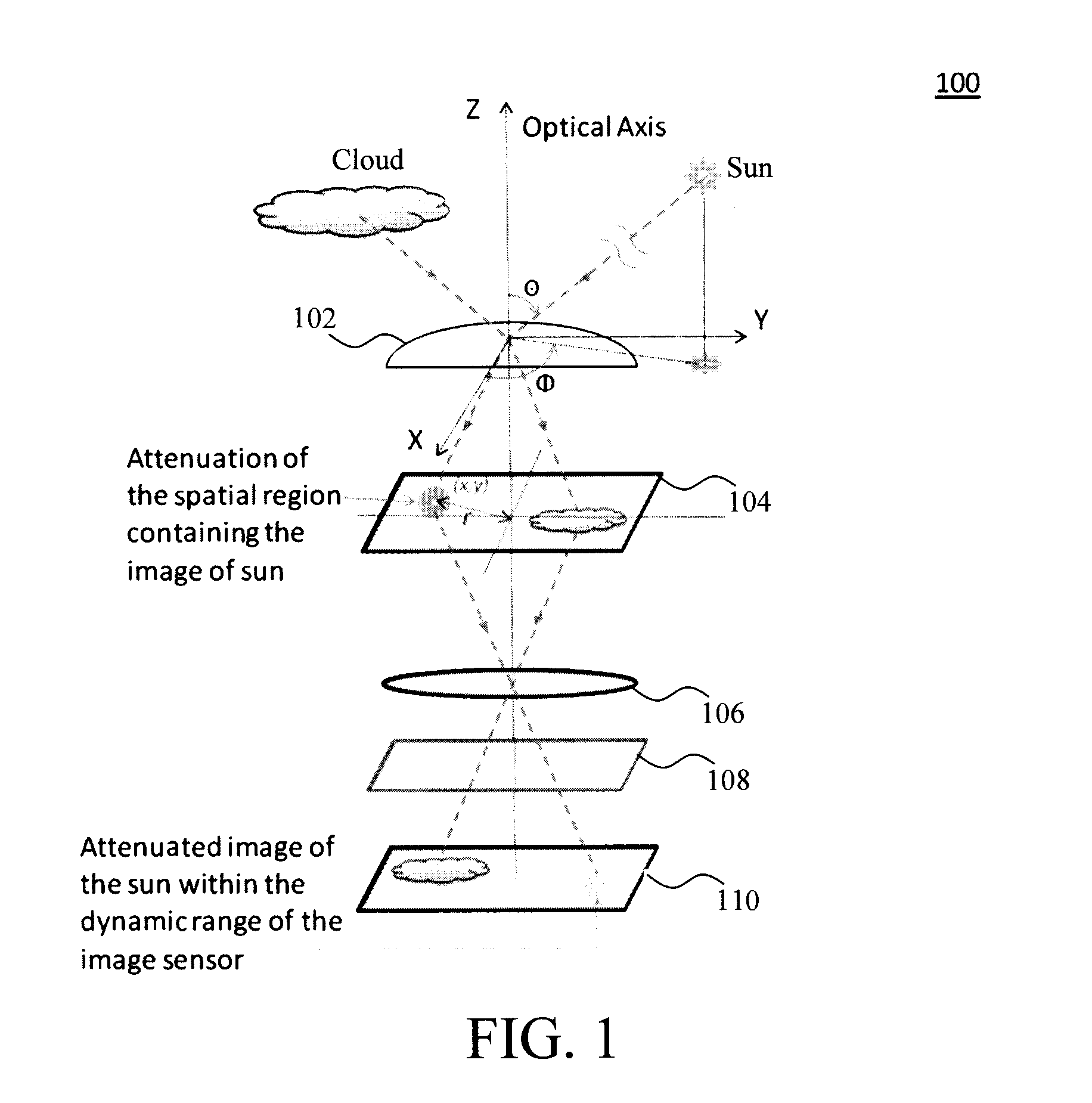
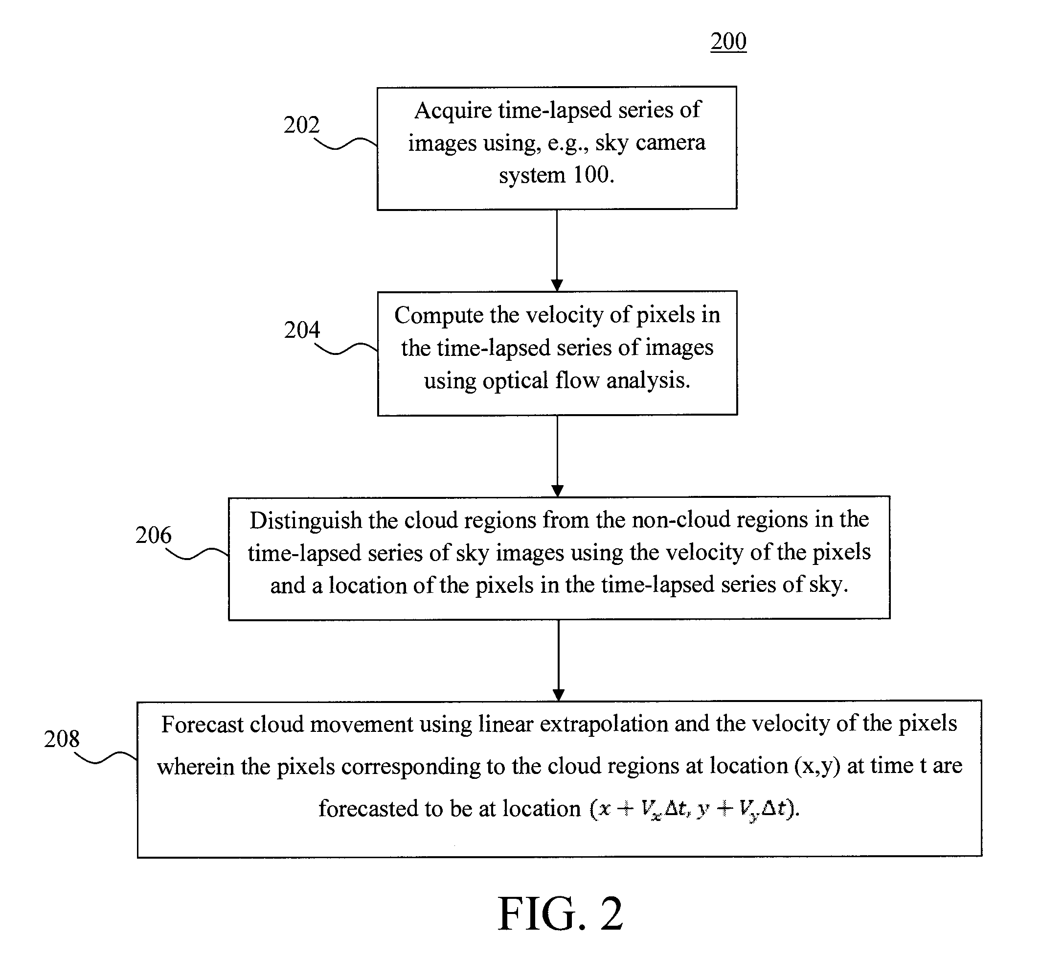
[0021]Provided herein is a sky camera-based multifunctional system that may be used for sky imaging, radiation measurement, and two- and three-dimensional cloud analysis. Both the design of the sky camera system and analysis methods based on images acquired using such a sky camera system are described in detail below.

[0022]The present sky camera system combines an image sensor with spatial light modulator to achieve the necessary ˜106 dynamic range to cover dim twilight and direct sun and thus circumvents the need for mechanical sun blocking as in conventional systems (see above). As will be described in detail below, the present camera system is multifunctional as it can be used not only for imaging but also for gathering complete spatially and spectrally resolved sky radiation information in the ultraviolet (UV), visible (Vis), near-infrared (NIR) regime most relevant to solar power forecasting applications. Further, with the appropriate semiconductor image sensors (see below), th...


PUM


Abstract

A multifunctional sky camera system and techniques for the use thereof for total sky imaging and spectral irradiance / radiance measurement are provided. In one aspect, a sky camera system is provided. The sky camera system includes an objective lens having a field of view of greater than about 170 degrees; a spatial light modulator at an image plane of the objective lens, wherein the spatial light modulator is configured to attenuate light from objects in images captured by the objective lens; a semiconductor image sensor; and one or more relay lens configured to project the images from the spatial light modulator to the semiconductor image sensor. Techniques for use of the one or more of the sky camera systems for optical flow based cloud tracking and three-dimensional cloud analysis are also provided.

Description

CROSS-REFERENCE TO RELATED APPLICATION(S)[0001]This application is a continuation of U.S. application Ser. No. 13 / 873,653 filed on Apr. 30, 2013, the disclosure of which is incorporated by reference herein.FIELD OF THE INVENTION[0002]The present invention relates to total sky imaging techniques and more particularly, to a multifunctional sky camera system and techniques for the use thereof for total sky imaging as well as spectrally-revolved irradiance / radiance measurement.BACKGROUND OF THE INVENTION[0003]Total sky imaging systems are powerful tools for various scientific and industrial applications such as high resolution cloud tracking and short-term (less than one hour) solar power forecasting. The contrast required by sky imaging (1:1,000,000), however, far exceeds the capability of currently available digital imaging sensors (typically 1:1,000 or less dynamic range). A cloudy twilight sky (no direct sun) has a radiance of ˜0.1 milliwatts per square centimeter steradian (mW / cm2s...

Claims


Application Information

Patent Timeline
Patent Type & Authority Applications(United States)
IPC IPC(8): H04N5/359G06T7/20H04N5/238
CPCH04N5/3591G06T7/20H04N5/238G01W1/12G06T5/008G06T2207/10021G06T7/85G06T7/593G06T7/215H04N13/239H04N23/60H04N23/698H04N23/75H04N25/621H04N23/69
Inventor HAMANN, HENDRIK F.LU, ZIYUAN
Owner IBM CORP
Learn More