
Operation planning system and method for creating operation plan

a technology of operation planning and operation plan, applied in adaptive control, process and machine control, instruments, etc., can solve problems such as false operation of electrical equipment, and achieve the effect of reducing environmental load

Inactive Publication Date: 2014-11-06
KK TOSHIBA
View PDF2 Cites 11 Cited by
  • Summary
  • Abstract
  • Description
  • Claims
  • Application Information

AI Technical Summary

Benefits of technology

The present patent provides a method for creating an operation schedule for a power system by combining power generation quantities of various power sources to match a power demand curve, while considering the environmental load information of the power sources. The method calculates the environmental load index to supply quantity and the reducible index obtained by dividing the reducible supply quantity by the necessary reduction quantity. The method determines whether the environmental load index and the reducible index are within certain ranges and adjusts the supply curve accordingly. The technical effect is a more efficient and flexible power system operation that considers both environmental load and reducible supply quantity, resulting in better cost savings and improved reliability.

Problems solved by technology

When the demand / supply of power becomes unbalanced, a frequency and a voltage become varied, which may cause a false operation of electrical equipment.

Method used


Image

  • Operation planning system and method for creating operation plan
  • Operation planning system and method for creating operation plan
  • Operation planning system and method for creating operation plan

Examples


first embodiment

[0028](General Structure)

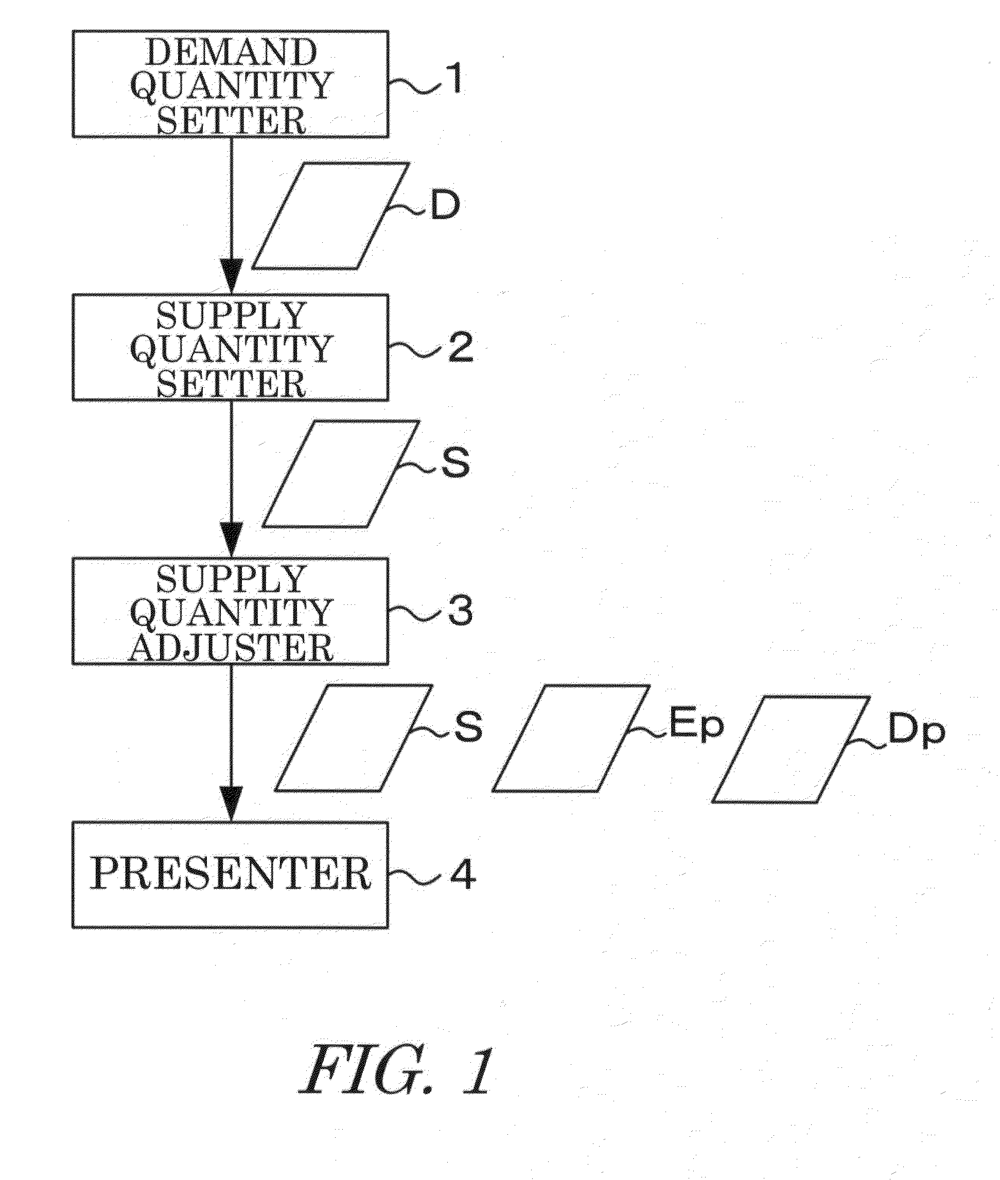
[0029]FIG. 1 is a block diagram illustrating a general structure of an operation planning system according to a first embodiment. The operation planning system illustrated in FIG. 1 is a single computer or distributed computers, allows a CPU to execute a process in accordance with a program stored in advance, and includes a demand quantity setter 1, a supply quantity setter 2, a supply quantity adjuster 3, and a presenter 4.

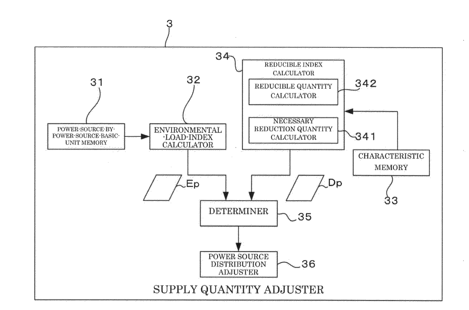
[0030]This operation planning system creates an operation schedule that adjusts a supply quantity in such a way that a reducible index Ds does not become equal to or smaller than a certain value while suppressing an environmental load index Ep to be equal to or smaller than a certain level upon reduction of a supply and also suppressing power saving forced to consumers and originating from the supply reduction to be within an acceptable range, thereby accomplishing a balancing with a demand as needed.

[0031]The environmental load index Ep ...

second embodiment

[0112](Structure)

[0113]Next, a detailed explanation will be given of an operation planning system and an operation schedule creating method according to a second embodiment with reference to the accompanying drawings. The same structure as that of the first embodiment will be denoted by the same reference numeral, and the detailed explanation thereof will be omitted.

[0114]FIG. 12 is a block diagram illustrating a structure of an operation planning system according to the second embodiment. As illustrated in FIG. 12, this operation planning system includes a transmitter 5 and a collector 6.

[0115]The transmitter 5 includes a CPU and a network adapter, and transmits messages to absorb the opinions of the consumers to each consumer. This message is an inquiry as to whether or not the power consumption that should be suppressed by the consumers is realizable. The power consumption that should be suppressed by the consumers is, in other words, a supply quantity reduced through an adjustme...


PUM


Abstract

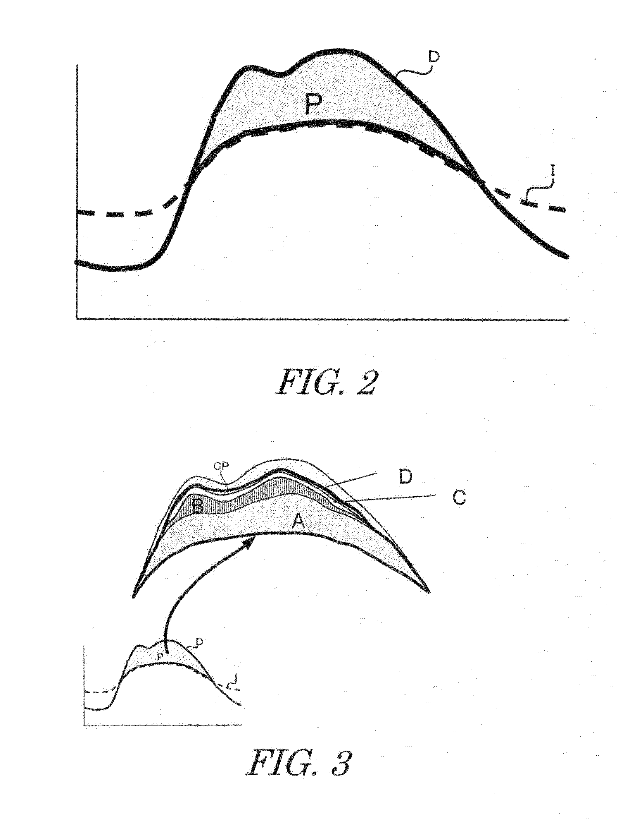
A power supply curve matching one of the patterns of a demand curve stored in advance is created by combining power generation quantities of various power sources. An environmental load index to a supply quantity indicated by the supply curve is calculated based on environmental load information stored in advance. Next, reducible quantity information for each power consumption reduction characteristic of each consumer is stored in advance, a necessary reduction quantity to cause the supply curve to match a predetermined curve is calculated. A reducible supply quantity is calculated based on reducible quantity information, and a reducible index obtained by dividing the reducible supply quantity by the necessary reduction quantity is calculated. Next, the supply curve is adjusted until it is determined that both environmental load index and the reducible index are within respective certain ranges.

Description

TECHNICAL FIELD[0001]Embodiments of the present disclosure relates to an operation planning system that predicts a power demand and creates operation schedules of various power sources, and a method for creating an operation schedule executed by the same.BACKGROUND ART[0002]Power is generated based on the rule of balancing. That is, with respect to power, a demand and a supply should be equal, and a power generation quantity and a power consumption quantity should be the same quantity. When the demand / supply of power becomes unbalanced, a frequency and a voltage become varied, which may cause a false operation of electrical equipment. Hence, electricity companies predict the demand for power in advance, and create operation schedules of various power sources, such as renewable energy power generation including solar power generation, geothermal power generation, and wind power generation, nuclear power generation, water power generation, thermal power generation, and geothermal powe...

Claims


Application Information

Patent Timeline
Patent Type & Authority Applications(United States)
IPC IPC(8): G05B13/02G06Q50/06
CPCG05B13/02G06Q50/06G06Q10/06313H02J3/48Y02B70/3225Y04S20/222H02J2310/12H02J2300/20H02J3/381H02J3/14H02J3/466H02J2310/60H02J3/00H02J13/00
Inventor OBARA, REIKONODA, HIDEKIKOBAYASHI, TAKENORIISOGAI, TAICHIYAMADA, TAKAHIRO
Owner KK TOSHIBA
Learn More