Bolt connection assembly for a wind turbine lattice tower structure

a technology of bolt connection and wind turbine, which is applied in the manufacture of threaded fasteners, screwdrivers, and final products, etc., can solve the problems of increasing construction time, increasing construction costs, and increasing construction costs, so as to improve the reliability of the connection

Inactive Publication Date: 2014-11-13
GENERAL ELECTRIC CO
View PDF18 Cites 14 Cited by
  • Summary
  • Abstract
  • Description
  • Claims
  • Application Information

AI Technical Summary

Benefits of technology

[0010]In still additional embodiments, the shaft of the bolt component may further include a threaded end section. As such, the bolt component may be drawn within the bore or aligned bores by the threaded end section. Further, the threaded end section may be engaged by a nut component and a washer component, wherein the nut component is configured to give the bolt component a predetermined preload. Moreover, the washer component may be assembled between the structural members and the nut component so as to provide a more even load on the bolt component. Additionally, the washer component may be a wedge-style, a ramp-style washer, or similar. More specifically, the washer component may be a wedge-locking washer. As such, the combination of the friction fit between the knurled surface and the bore component together with the preload provided by the torqued nut component and the wedge-locking washer contributes to improved joint reliability in a wind turbine lattice structure.

Problems solved by technology

However, tubular poles use more steel than lattice structures, resulting in a cost disadvantage with the rising prices of steel.
The lattice structure, however, is relatively more complex due to numerous joints.
Such joints increase construction time and present possible locations for wear and maintenance.
Although this bolt connection may provide a relatively good balance between strength and maintenance, the preload may be difficult to control and maintain in wind turbine lattice tower structures, which commonly experience cyclic loading.
As such, slippage is a concern in lattice tower structures and may cause mechanical wear of the structural members, loosening of the fasteners and / or bolts, or loss of structural integrity.

Method used


Image

  • Bolt connection assembly for a wind turbine lattice tower structure
  • Bolt connection assembly for a wind turbine lattice tower structure
  • Bolt connection assembly for a wind turbine lattice tower structure

Examples


Embodiment Construction

[0032]Reference now will be made in detail to embodiments of the invention, one or more examples of which are illustrated in the drawings. Each example is provided by way of explanation of the invention, not limitation of the invention. In fact, it will be apparent to those skilled in the art that various modifications and variations can be made in the present invention without departing from the scope or spirit of the invention. For instance, features illustrated or described as part of one embodiment can be used with another embodiment to yield a still further embodiment. Thus, it is intended that the present invention covers such modifications and variations as come within the scope of the appended claims and their equivalents.

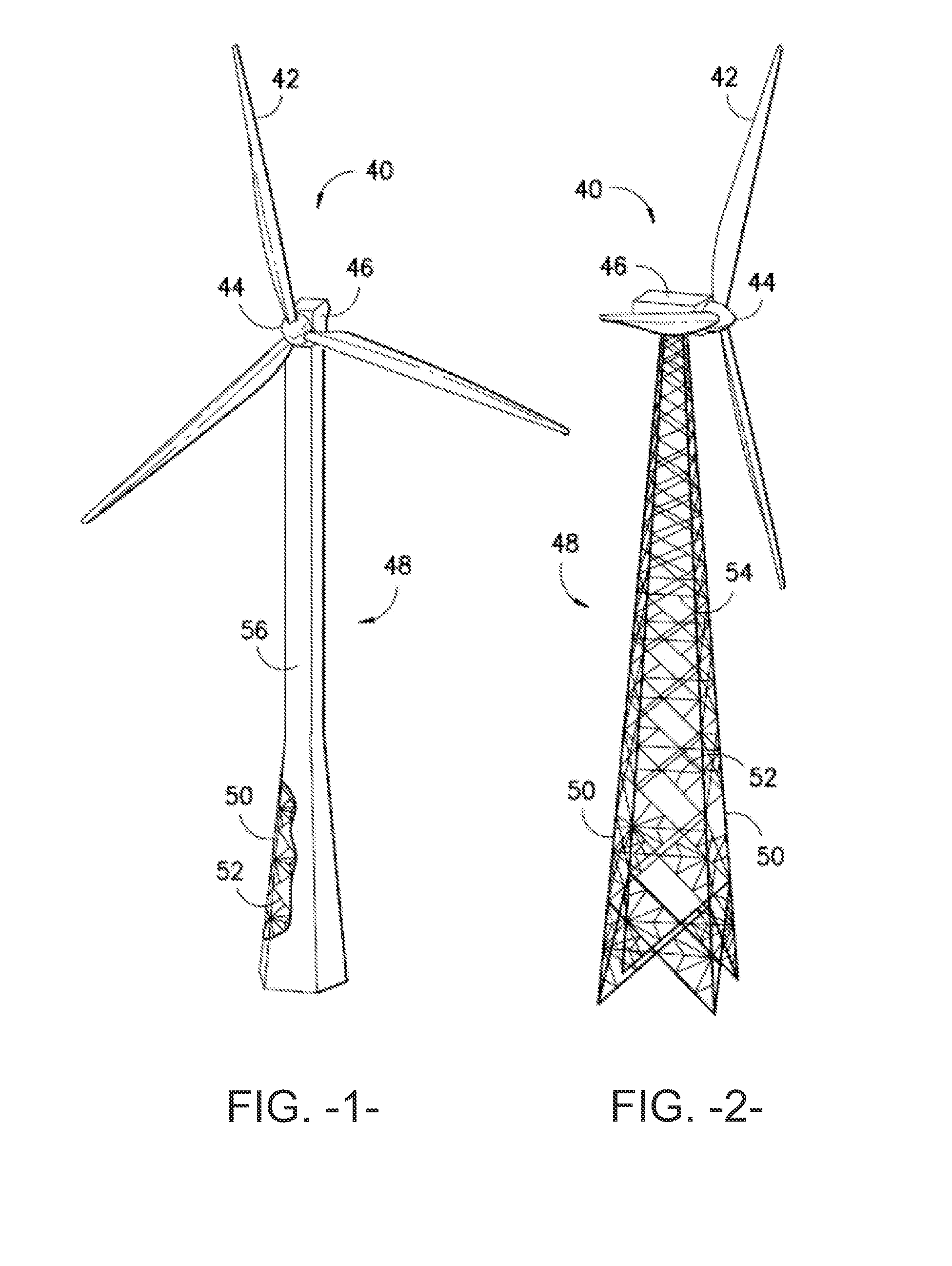
[0033]FIGS. 1 and 2 are perspective views of exemplary wind turbines 40. The wind turbines 40 include a plurality of blades mounted to a rotor hub 44, which in turn is rotationally supported by any manner of power generation components housed within a nacel...


PUM


Abstract

A bolt connection assembly is provided that is particularly well-suited for connecting structural members of a lattice tower structure for a wind turbine. The bolt connection assembly includes a bolt component having a head and a shaft and a structural bore component having a bore defined therethrough for receipt of the bolt component. The shaft includes a knurled surface such that the knurled surface defines an outermost shaft diameter. Moreover, the knurled surface includes a plurality of knurls, each defining a non-arcuate edge. The bore defines a bore diameter, wherein the outermost shaft diameter is greater than the bore diameter. In an assembled state of the bolt component and the structural bore component, the bolt component may be inserted within the bore such that the knurled surface may be deformed to friction fit within the bore diameter.

Description

FIELD OF THE INVENTION[0001]The present invention relates generally to wind turbine tower structures, and more particularly to a bolt connection assembly for a lattice tower structure.BACKGROUND OF THE INVENTION[0002]Wind power is considered one of the cleanest, most environmentally friendly energy sources presently available, and wind turbines have gained increased attention in this regard. A modern wind turbine typically includes a tower, a generator, a gearbox, a nacelle, and a rotor. The rotor typically includes a rotatable hub having one or more rotor blades attached thereto. A pitch bearing is typically configured operably between the hub and the rotor blade to allow for rotation about a pitch axis. The rotor blades capture kinetic energy of wind using known airfoil principles. The rotor blades transmit the kinetic energy in the form of rotational energy so as to turn a shaft coupling the rotor blades to a gearbox, or if a gearbox is not used, directly to the generator. The ge...

Claims


Application Information

Patent Timeline
Patent Type & Authority Applications(United States)
IPC IPC(8): F16B39/28E04H12/00
CPCF16B39/28E04H12/00E04H12/10F16B4/004F05B2230/60F05B2240/9121F05B2250/61F05B2260/301Y02E10/728F16B5/02F16B39/24F03D13/20Y02P70/50Y02E10/72F03D13/10E04H12/08
Inventor ANDERSEN, TODD D.OLIPHANT, DAVID D.
Owner GENERAL ELECTRIC CO
Why Eureka
Try Eureka