
Sample introduction device and method

a technology of sample introduction and sample, which is applied in the direction of electric/magnetic/electromagnetic heating, magnetic bodies, instruments, etc., can solve the problems of small sample volume that should be used, contamination of injectors, and difficult doses, so as to improve the control of spatial temperature profile or gradient, reduce the distance between the windings of the coil for inductive heating, and improve the effect of spatial temperature profil

Inactive Publication Date: 2014-11-13
DSM IP ASSETS BV
View PDF4 Cites 23 Cited by
  • Summary
  • Abstract
  • Description
  • Claims
  • Application Information

AI Technical Summary

Benefits of technology

The injector described in this patent allows for gas phase analysis with reduced discrimination. This is achieved through well-controlled heating and a specific temperature profile from sample inlet to column outlet. The use of induction heating means ensures even heating of the housing and prevents the formation of cold spots that could cause unwanted condensation of higher boiling compounds. The liner / sample container and optional sample retainer are made of inert material that does not interact chemically with the sample and has low magnetic permeability, resulting in a more homogeneous and controllable heating of the liner.

Problems solved by technology

This explosive and uncontrolled growth in volume within the liner, which typically has a volume of about 0.5-1 ml, may result in non-plug flow of sample / carrier gas, and in sample even going against the carrier gas flow resulting in contamination of the injector.
Theoretically this technique provides almost ideal sample introduction with respect to discrimination, but disadvantages include the very small sample volume that should be used (which is difficult to dose), and possible column contamination with non-volatile compounds present in the sample.
A drawback of the known injectors is that the discrimination effect is not completely overcome, specifically not for samples containing less volatile compounds.

Method used


Image

  • Sample introduction device and method
  • Sample introduction device and method
  • Sample introduction device and method

Examples


example

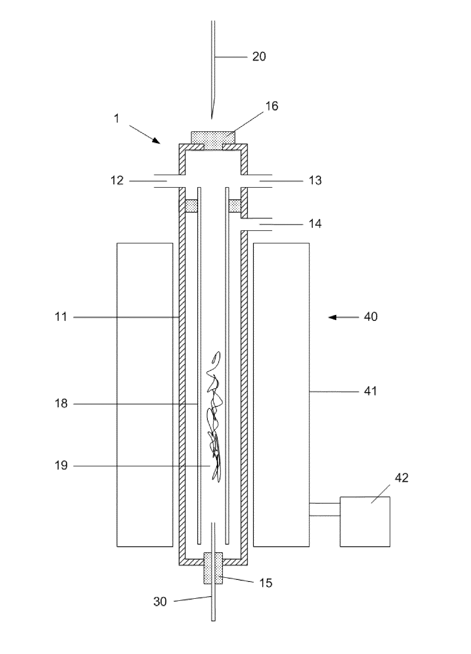
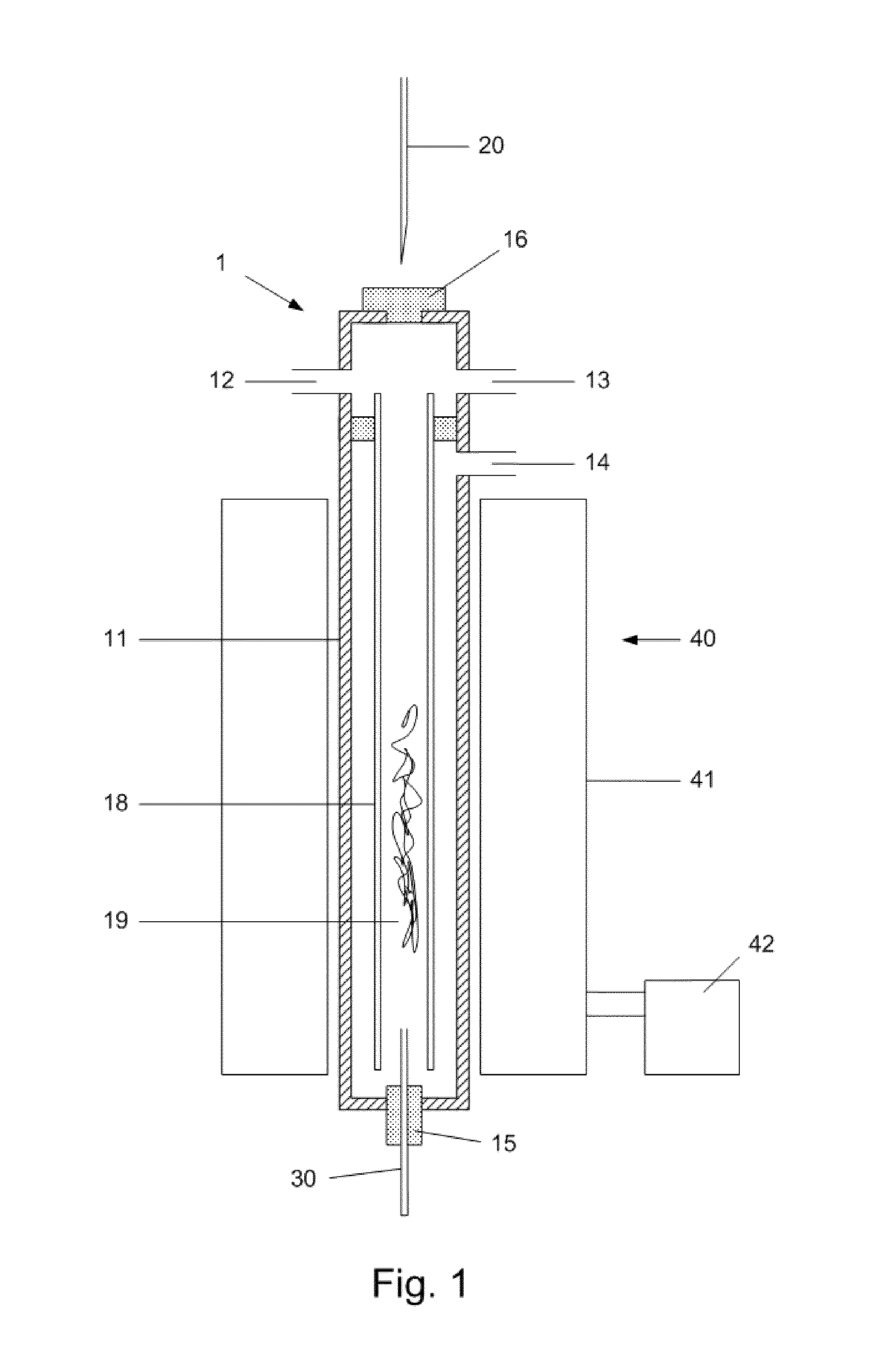
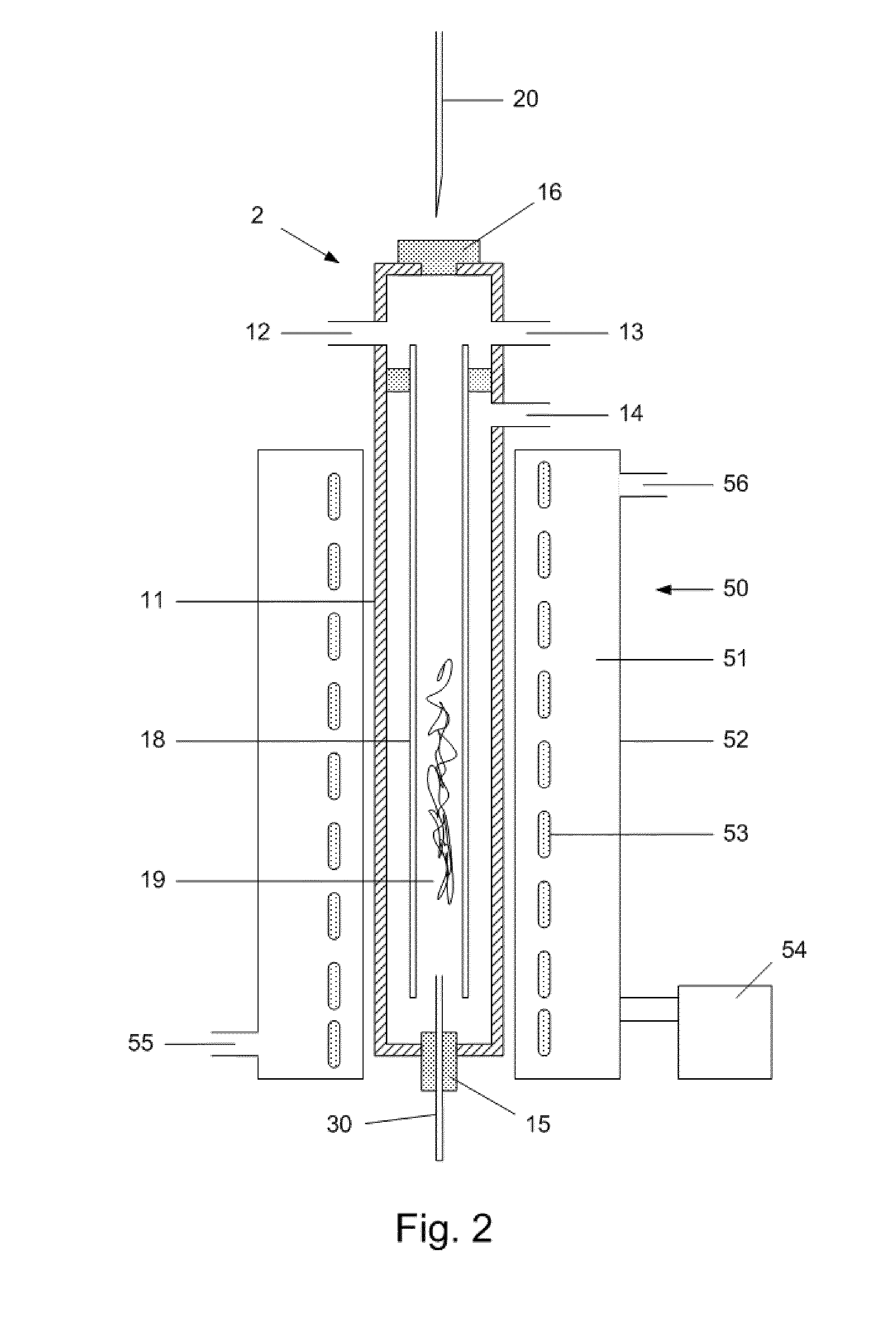
[0082]The performance of an injector according to the invention having a metal housing with coils for inductive heating arranged around the housing was tested and compared to a cold-on-column experiment under similar conditions.

Test a:

[0083]A sample was prepared and gas chromatographic analysis was conducted on an Agilent 5890 series II with an injector according to the invention under the following settings

[0084]Sample:

[0085]Material: Polywax 655

[0086]Solvent: toluene

[0087]External calibration: C28

[0088]Column: J&W DB-HT Simdis(145-1001)

[0089]Dimensions: 5 m*0.53 mm*0.15 um

[0090]Carrier gas: Helium

[0091]Start temp: 50° C.

[0092]Ramp 1: 50° C.-350° C., 10° C. / min

[0093]Ramp 2: 350° C.-430° C., 5° C. / min

[0094]End temp: 430° C. (for 5 minutes)

[0095]Injector

[0096]House: Agilent housing where conductive heater is removed and replaced by coils for inductive heating.

[0097]Coil: 10 double windings of copper band (5×2 mm) isolated by glass tubes. Winding density towards sample inlet about 4-...


PUM

PropertyMeasurementUnit
temperatureaaaaaaaaaa
temperaturesaaaaaaaaaa
volumeaaaaaaaaaa

Abstract

The present invention relates to an injector for use in gas phase analytical systems and methods comprising a metal housing, provided with a carrier gas inlet, a split outlet, a column outlet of the injector, a sample inlet, a liner, and a heater device comprising at least one coil for radio frequency inductive heating the housing with a predetermined temperature program and for providing a predetermined spatial temperature profile in the injector. The injector according to the invention allows performing gas phase analyses, especially GC analyses with reduced discrimination. Advantages of heating with a heater device comprising a coil for inductive heating include a homogeneous heating profile of the housing including parts connected thereto, with heating rates that can be varied widely. A further advantage is that the injector can be operated as a conventional S / SL injector at a predetermined temperature, or as PTV injector or thermal desorption injector with certain predetermined temperature programs. The invention also relates to a process of making an injector according to the invention, and to a process of refitting an existing S / SL injector. The invention further concerns a gas analytical system comprising an injector according to the invention, and to a process of analysing a sample with such gas analytical system.

Description

TECHNICAL FIELD[0001]The present invention relates generally to gas phase analytical techniques, like gas chromatography (GC), and more specifically to a sample introduction device (hereinafter also called injector) for use in gas phase analytical systems and methods. In particular the invention relates to a Programmed Temperature Vaporising (PTV) injector.[0002]The present invention also relates to a process of making an injector according to the invention, and to refitting an existing split / splitless (S / SL) injector with a heater device forming part of the injector of the invention. The invention further concerns a gas phase analytical system comprising an injector of the invention, and a process of analysing a sample with such a gas analytical system, like a GC system.BACKGROUND ART[0003]Gas chromatography is a commonly applied gas phase analytical technique for analysing a sample, which sample may include one or more compounds (also called analytes) that can be vaporised. GC can...

Claims


Application Information

Patent Timeline
Patent Type & Authority Applications(United States)
IPC IPC(8): G01N30/16H01F41/04H05B6/36
CPCG01N30/16H05B6/36H01F41/04G01N30/12G01N2030/127Y10T29/49073
Inventor VAN EGMOND, WILHELM MATTHIJS ADRIAANMENGERINK, YNZE
Owner DSM IP ASSETS BV
Learn More