Current efficient electrolytic device and method

a current efficient and electrolytic technology, applied in electrodialysis, diaphragms, refrigeration components, etc., can solve the problems of high background noise, high current, and heat generation

Active Publication Date: 2014-11-13
DIONEX CORP
View PDF6 Cites 20 Cited by
  • Summary
  • Abstract
  • Description
  • Claims
  • Application Information

AI Technical Summary

Benefits of technology

[0007]One embodiment is an apparatus for treating an aqueous stream, said apparatus comprising a first ion exchange membrane having exchangeable ions of a first charge and capable of passing ions of said first charge, an aqueous stream flow channel having an inlet and an outlet, an ion receiving flow channel adjacent to said aqueous stream flow channel and separated therefrom by said first membrane, stationary flow-through ion exchange packing of the same charge as said ion exchange membrane disposed in said ion receiving flow channel, a packed bed of ion exchange particles disposed in and extending between said aqueous stream flow channel inlet and outlet, a portion of said packed bed being packed at a density less than 2 grams of packed dry particles per cc of the sample stream flow channel, said packed bed portion extending from

Problems solved by technology

Under high eluent concentration conditions, this high curren

Method used


Image

  • Current efficient electrolytic device and method
  • Current efficient electrolytic device and method
  • Current efficient electrolytic device and method

Examples


example 1

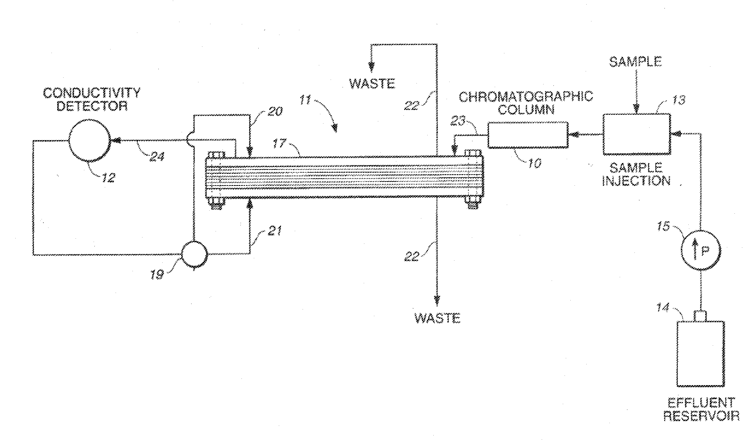
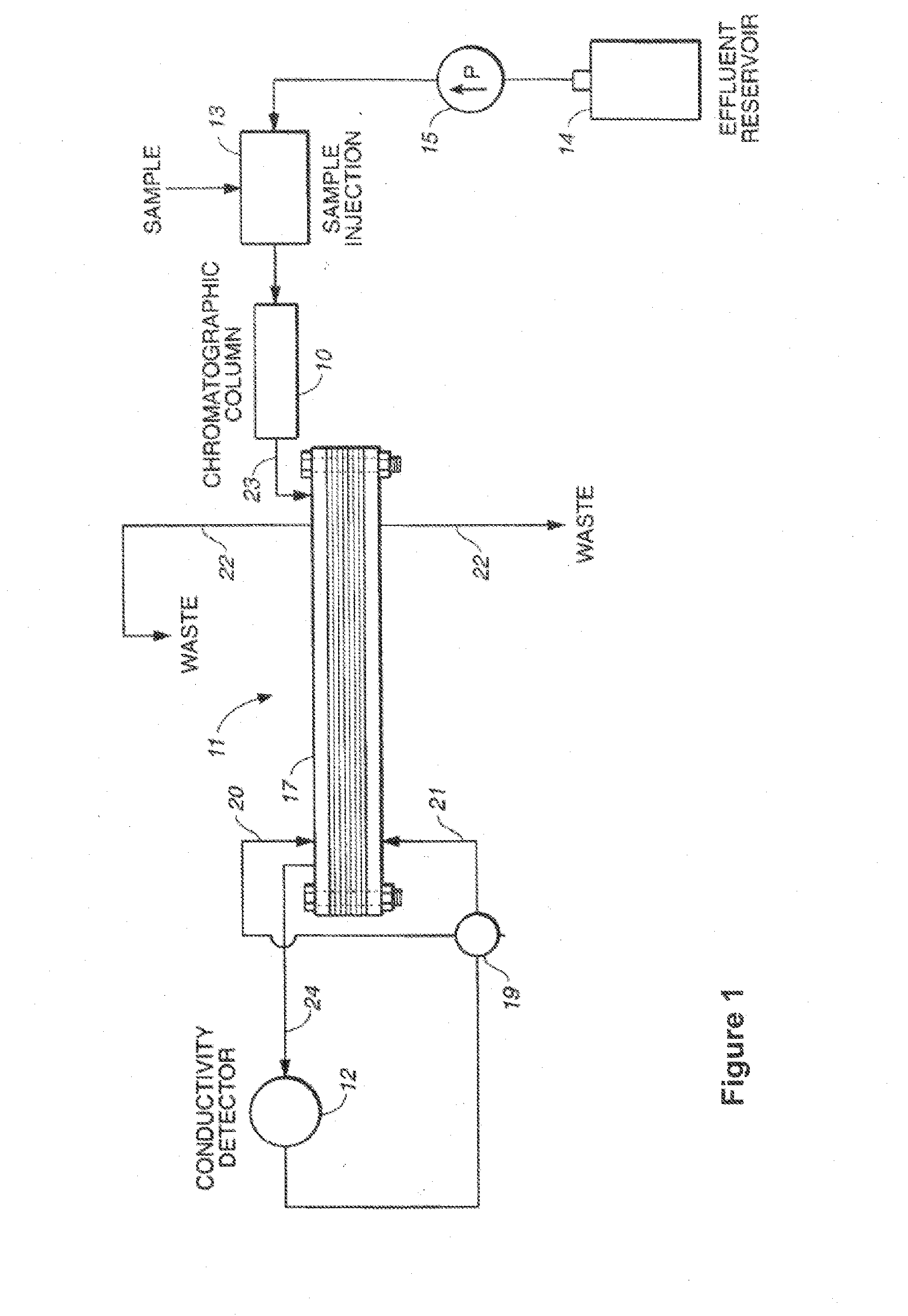
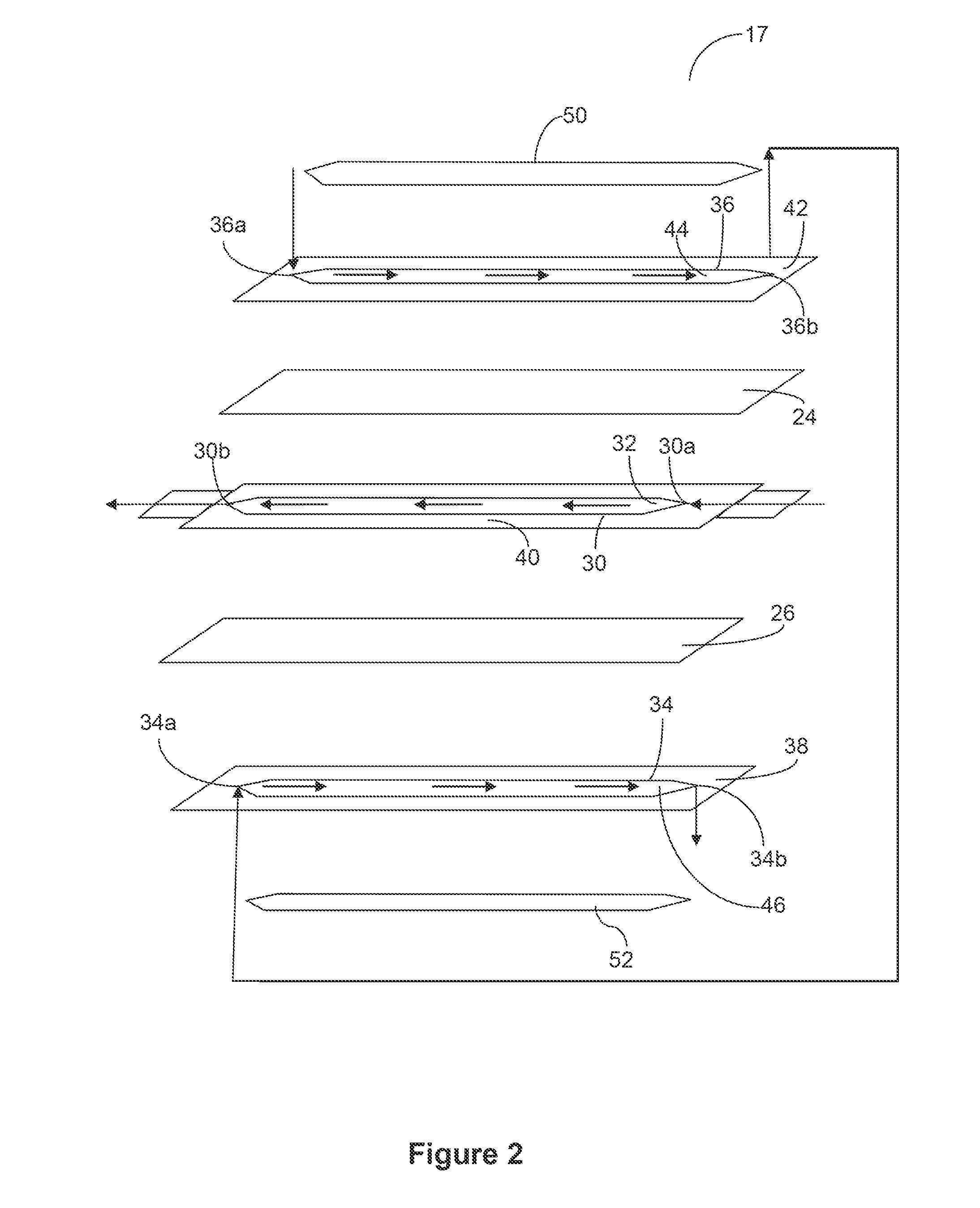
[0059]A 4 mm anion self-regenerating suppressor (ASRS) was assembled and plumbed following the schematic of FIG. 2. A polystyrene divinyl benzene based sulfonated cation exchange resin that had 16% crosslinking was used. The capacity of this resin was 2.0 meqv / mL. Approximately 0.4 g of the resin was placed along the total length of the eluent sample stream channel in a dry form to provide a density of 1.62 grams / cc. Cationic ion exchange screens were placed in the regenerant channels. Once the device was assembled and the device was hydrated it was ready for use. The static capacity was measured and was roughly 2.0 meqv for the eluent channel that included the exchange capacity of the ion exchange membranes and the ion exchange resin. The static capacity calculated was 7.4 meqv / mL of the sample stream flow channel. The static capacity of a standard commercial suppressor sold under the name 4 mm ASRS 300 was roughly 270 μeqv. The static capacity calculated was approximately 1.0 meqv...

example 2

[0061]A 2 mm ASRS suppressor was assembled and plumbed following the schematic of FIG. 2. The cation exchange resin from example 1 was used in this example. Approximately 0.08 g of dry resin was placed along the length in the eluent channel in a dry form. Cationic ion exchange screens were placed in the regenerant channels. Once the device was assembled and the device was hydrated it was ready for use. The static capacity was measured and was roughly 0.4 meqv for the eluent channel that included the exchange capacity of the ion exchange membranes and the ion exchange resin. The static capacity calculated was 6.84 meqv / mL of the sample stream flow channel. The static capacity of a standard commercial suppressor sold under the name 2 mm ASRS 300 was roughly 55 μeqv. The device of the present invention had roughly a greater than 7 fold higher capacity than the prior art. The static capacity calculated for the commercial device was 0.81 meqv / mL of the sample stream flow channel. The dev...

example 3

[0063]A 4 mm cation self-regenerating suppressor (CSRS) was assembled and plumbed following the schematic of FIG. 2. The anion exchange resin used was AG1 resin, 8% crosslinked with a capacity of 1.2 meqv / mL (Particle diameter 45-106 μm) sold by Bio-Rad, Hercules, Calif. Approximately 0.4 g was placed along the eluent channel in a dry form. Anion exchange screens were placed in the regenerant channels. Once the device was assembled and the device was hydrated it was ready for use. The static capacity was measured and was roughly 1.8 meqv for the eluent channel that included the exchange capacity of the ion exchange membranes and the ion exchange resin. The static capacity of a standard commercial suppressor sold under the name 4 mm CSRS 300 was roughly 600 μeqv. The device of the present invention had roughly a greater than 3 fold higher capacity than the prior art. The device was used as a suppressor for cation analysis using an IonPac CS12A (4×250 mm) column from Thermo Fisher Sci...


PUM

PropertyMeasurementUnit
Fractionaaaaaaaaaa
Massaaaaaaaaaa
Sizeaaaaaaaaaa

Abstract

A sandwich suppressor in an ion chromatography system in which loosely packed ion exchange resin of low density is disposed in the central sample stream flow channel. Also, a method of using the suppressor is described.

Description

BACKGROUND OF THE INVENTION[0001]One form of suppressor for ion chromatography is described in U.S. Pat. No. 4,999,098. The suppressor includes an ion receiving or regenerant channel and a sample stream or chromatographic effluent channel separated by an ion exchange membrane sheet. The sheet allows transmembrane passage of ions of the same charge as its exchangeable ions. Ion exchange screens are used in the channels. Flow from the sample flow channel is directed to a detector, such as an electrical conductivity detector, for detecting the resolved ionic species. The screens provide ion exchange sites and serve to provide site-to-site transfer paths across the sample flow channel so that suppression capacity is no longer limited by diffusion of ions in the bulk solution to the membrane. A sandwich suppressor is also disclosed including a second membrane sheet opposite to the first membrane sheet and defining a second channel. Spaced electrodes are disclosed in communication with bo...

Claims


Application Information

Patent Timeline
IPC IPC(8): C02F1/469
CPCC02F1/4695G01N30/56G01N30/96G01N2030/562G01N2030/965B01J39/26B01J41/20B01J47/12B01J49/30
Inventor SRINIVASAN, KANNANPOHL, CHRISTOPHER A.BHARDWAJ, SHEETALLIN, RONG
Owner DIONEX CORP
Why Eureka
Try Eureka