Eureka AIR delivers breakthrough ideas for toughest innovation challenges, trusted by R&D personnel around the world.

Electric waste gate control system sensor calibration with end-stop detection

a technology of waste gate control and sensor calibration, which is applied in the direction of electric control, instruments, machines/engines, etc., can solve the problems of waste gate valve impacting the valve seat at a high velocity, noise, vibration, and increased wear on the valve seat, etc., to achieve precise position control, faster response, and the effect of reducing the number of times

Active Publication Date: 2014-11-20
FORD GLOBAL TECH LLC
View PDF7 Cites 19 Cited by
  • Summary
  • Abstract
  • Description
  • Claims
  • Application Information

AI Technical Summary

Benefits of technology

The patent text describes a system for controlling engine boost using a waste gate valve. The system uses an electric actuator to adjust the position of the waste gate valve, which controls the amount of gas flow through the turbine. The electric actuator provides faster and more precise control than traditional pneumatic systems, increasing engine efficiency, fuel efficiency, and emissions control. The system also detects the end-stop position of the waste gate valve and provides feedback control to reduce impact and improve boost control accuracy. Overall, the technical effects of this system include increased control accuracy, reduced noise, and improved performance.

Problems solved by technology

However, the inventors herein have identified some potential issues with such an approach.
In the above described approach, the gear box output shaft sensor does not provide an indication of the waste gate valve position relative to a valve seat position.
Without knowing the end-stop of the waste gate valve, when the waste gate valve is commanded to a closed position the waste gate valve position may be adjusted too much causing the waste gate valve to impact the valve seat at a high velocity.
By adjusting the waste gate valve too much, noise, vibration, harshness (NVH) conditions and wear on the valve seat may be increased.
In addition, the closed-loop control system may apply too much current to the waste gate trying to move the waste gate valve to a desired stop position that is physically impossible to reach, leading to high stress in the whole system.
On the other hand, the waste gate valve position may be adjusted too little causing the waste gate valve to not properly seal with the valve seat resulting in undesired flow of gas through the waste gate that reduces boost pressure.
Furthermore, the waste gate valve and the plurality of linkages may be exposed to high temperatures within the turbine that can affect accuracy of the position sensor output.

Method used


Image

  • Electric waste gate control system sensor calibration with end-stop detection
  • Electric waste gate control system sensor calibration with end-stop detection
  • Electric waste gate control system sensor calibration with end-stop detection

Examples


Embodiment Construction

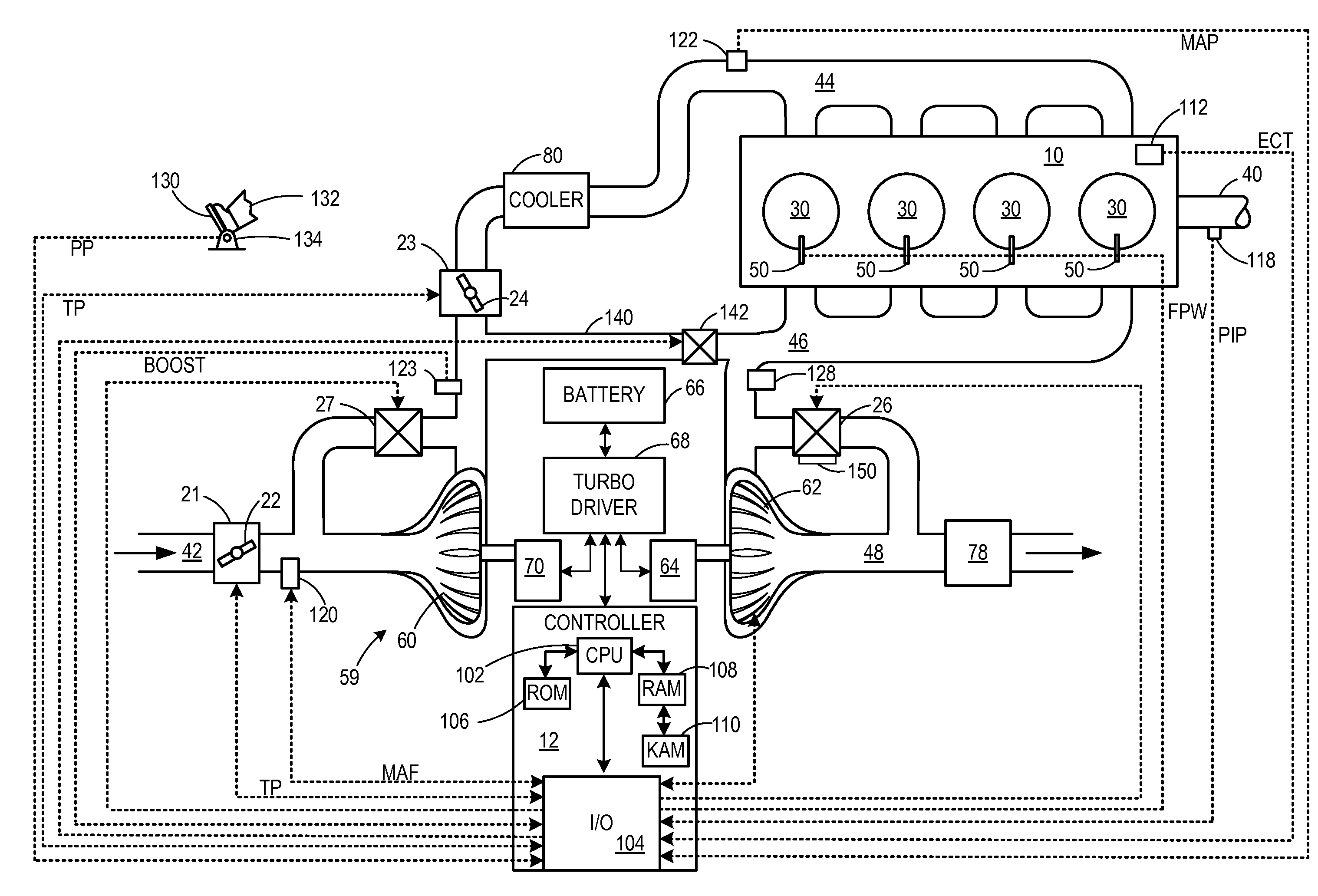
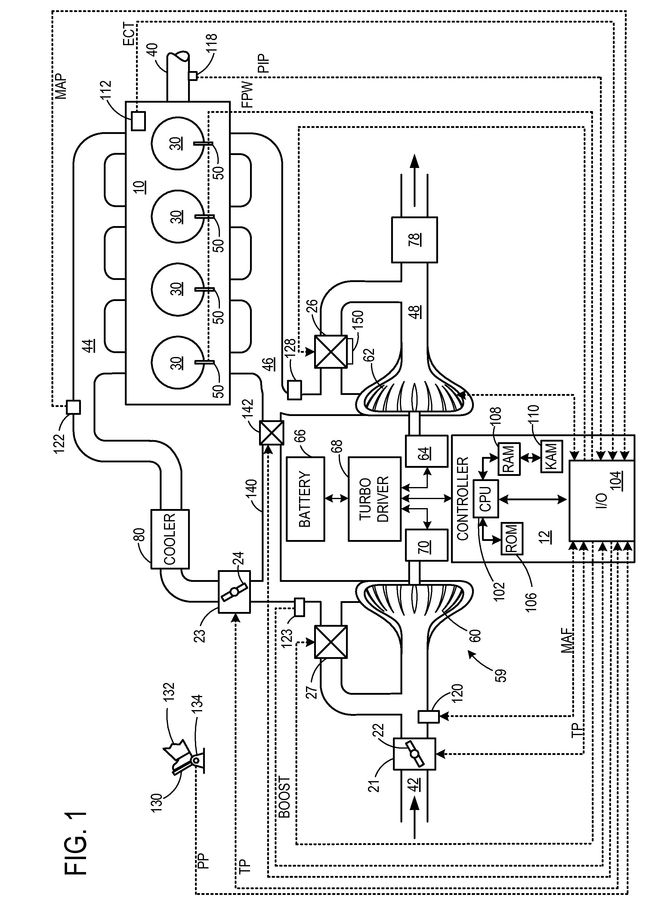
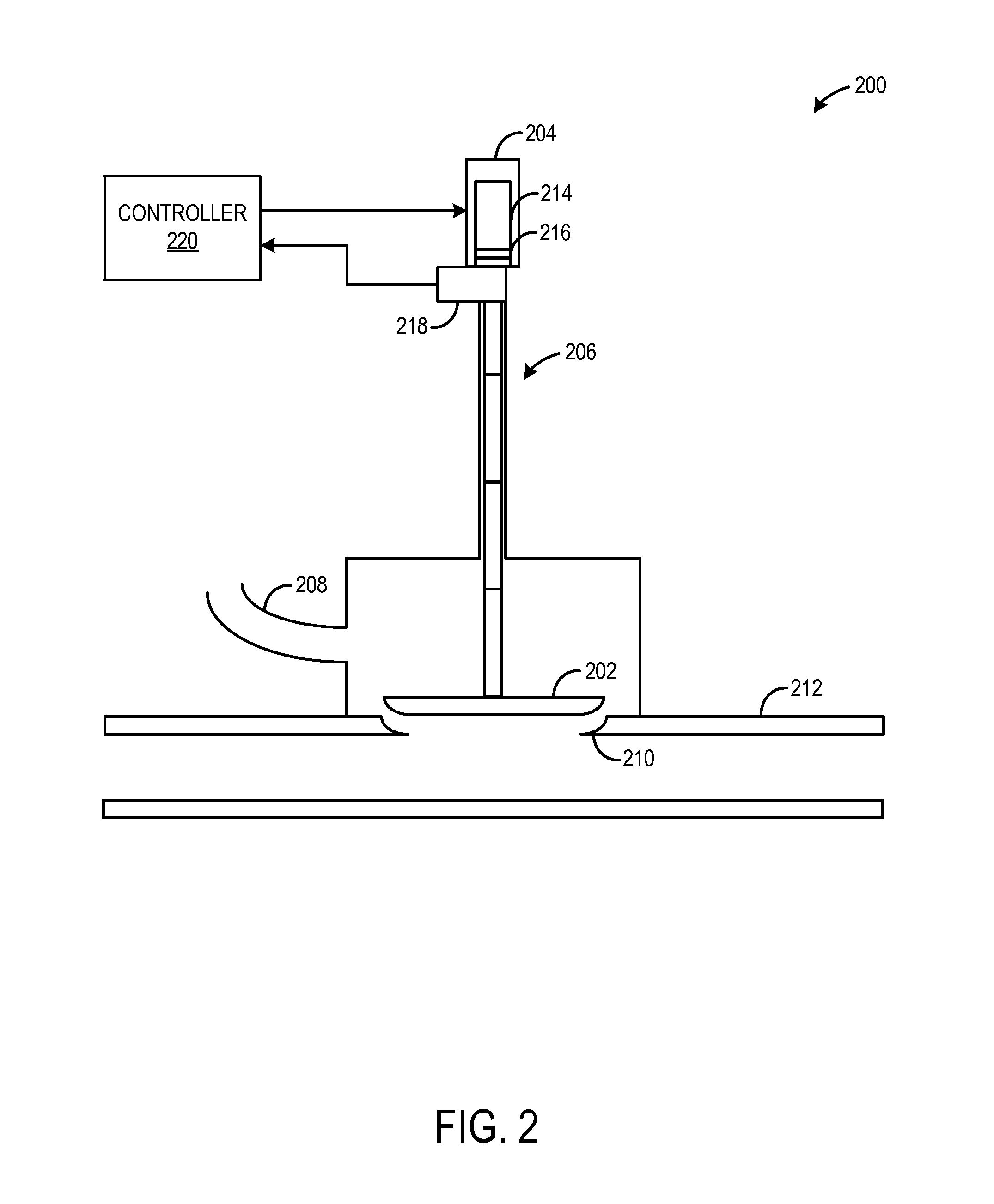
[0014]Various systems and methods are provided for detecting an end-stop position of a waste gate valve in a turbine of a turbocharger. The end-stop position of the waste gate valve may include a position where the waste gate valve suitably aligns with a valve seat to substantially prevent gas from flowing through the waste gate (e.g., less than 5% of total flow). On the other hand, the end-stop position may include a position where the waste gate valve is fully open.

[0015]In one example, an end-stop detection routine includes commanding a complete stroke of the waste gate valve from a completely open position to a completely closed position. When the waste gate valve is commanded to an end-stop position, a plurality of conditions may be checked to determine whether the waste gate valve is indeed positioned at an end-stop position. For example, the plurality of conditions may include a difference between a feedback position signal of the waste gate valve and a commanded position sig...


PUM


Abstract

Various embodiments relating to detection of an end-stop position of a waste gate valve and calibration of a waste gate position sensor relative to the detected end-stop position are provided. In this way, it is possible to more accurately control the waste gate.

Description

BACKGROUND AND SUMMARY [0001]Engine boost may be controlled by adjusting an amount of gas flowing through a turbine of a turbocharger, for example via a waste gate. In one example, a waste gate may include a waste gate valve and a valve seat. The waste gate valve may be actuated by an associated electric actuator. The electric actuator may be controlled to adjust a waste gate valve position, thereby controlling the amount of gas flowing through the turbine and achieving the desired boost. Electric waste gate actuation may provide a faster response and more precise position control relative to a pneumatically-actuated waste gate. The faster response and more precise control may increase engine efficiency, fuel efficiency and emissions control.[0002]In one example, an electric actuator that is used to control the position of a waste gate valve includes an electric motor which transmits a force to a plurality of linkages that are coupled to the waste gate valve. The plurality of linkag...

Claims


Application Information

Patent Timeline
IPC IPC(8): F02B37/22
CPCF02B37/22F01N2560/025F01N2560/06F02B29/04F02B37/186F02B37/16F02D41/08F02D41/123F02D41/2441F02D41/2474F02D41/0007F02M26/05F02D2250/16F02B37/162Y02T10/12F02B37/18G01M15/02G01M15/11
Inventor KOKOTOVIC, VLADIMIR V.WANG, YAN
Owner FORD GLOBAL TECH LLC
Why Eureka
Eureka Blog
Learn More