

Unit for recovering thermal energy from exhaust gas of an internal combustion engine
a technology for thermal energy recovery and internal combustion engines, which is applied in the direction of exhaust treatment, engine components, mechanical equipment, etc., can solve the problems of reducing the efficiency of heat recovery process, loss of heat from exhaust gas flowing, and only substantially closing of single valve flaps, so as to achieve smooth guide the exhaust gas flow and reduce the space consumption of the unit
- Summary
- Abstract
- Description
- Claims
- Application Information
AI Technical Summary
Benefits of technology
Problems solved by technology
Method used
Image

Examples
Embodiment Construction
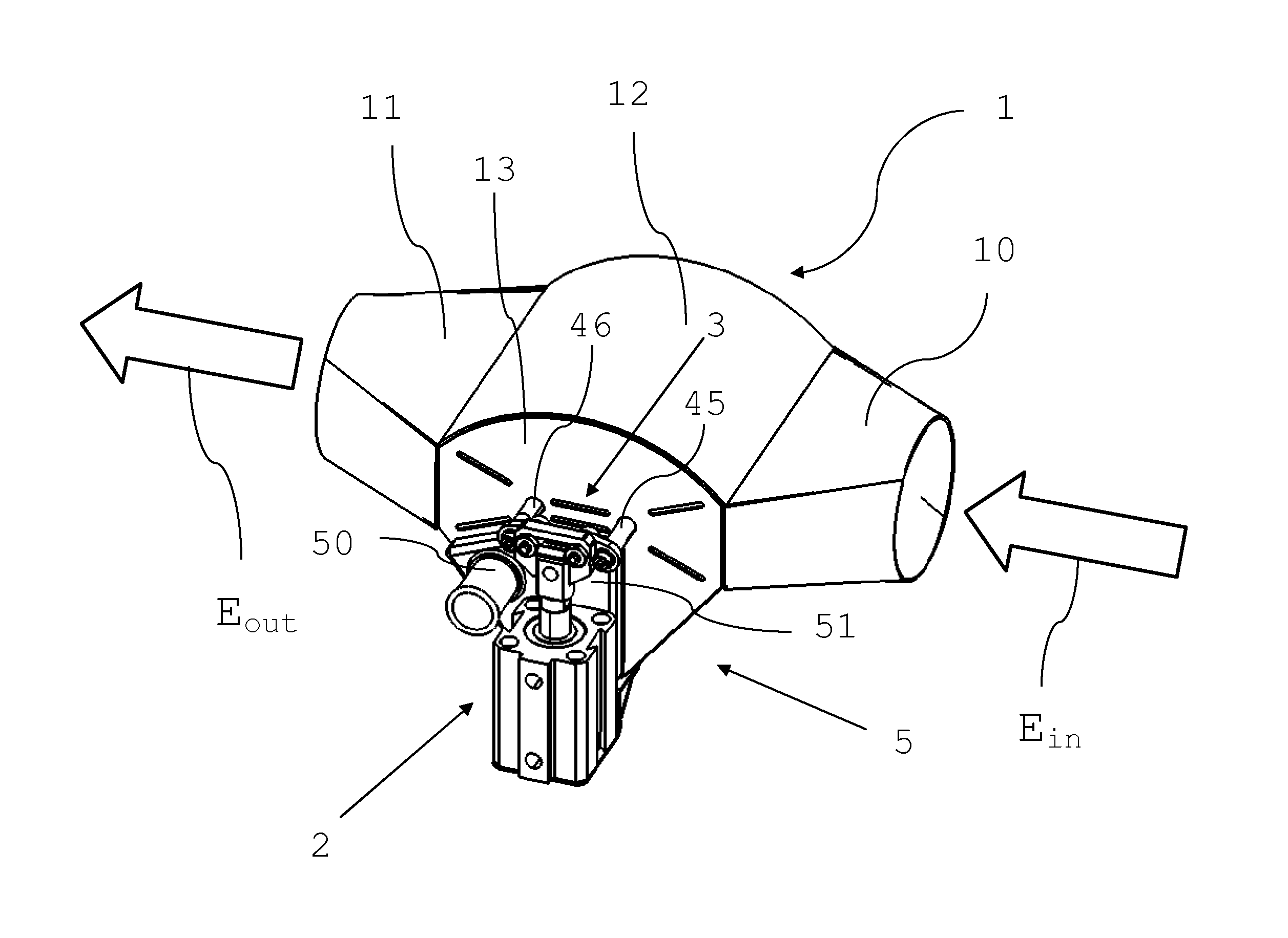
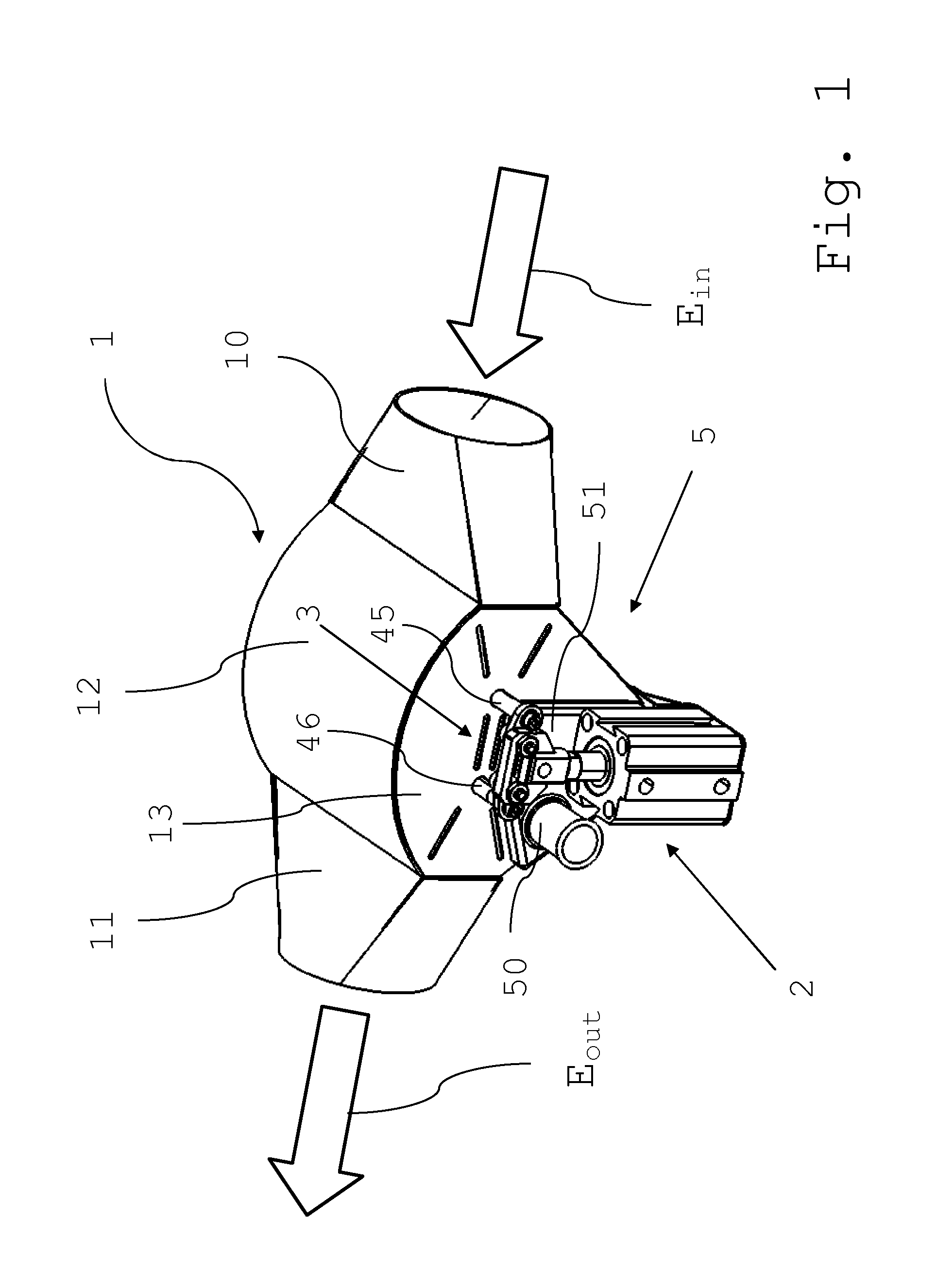
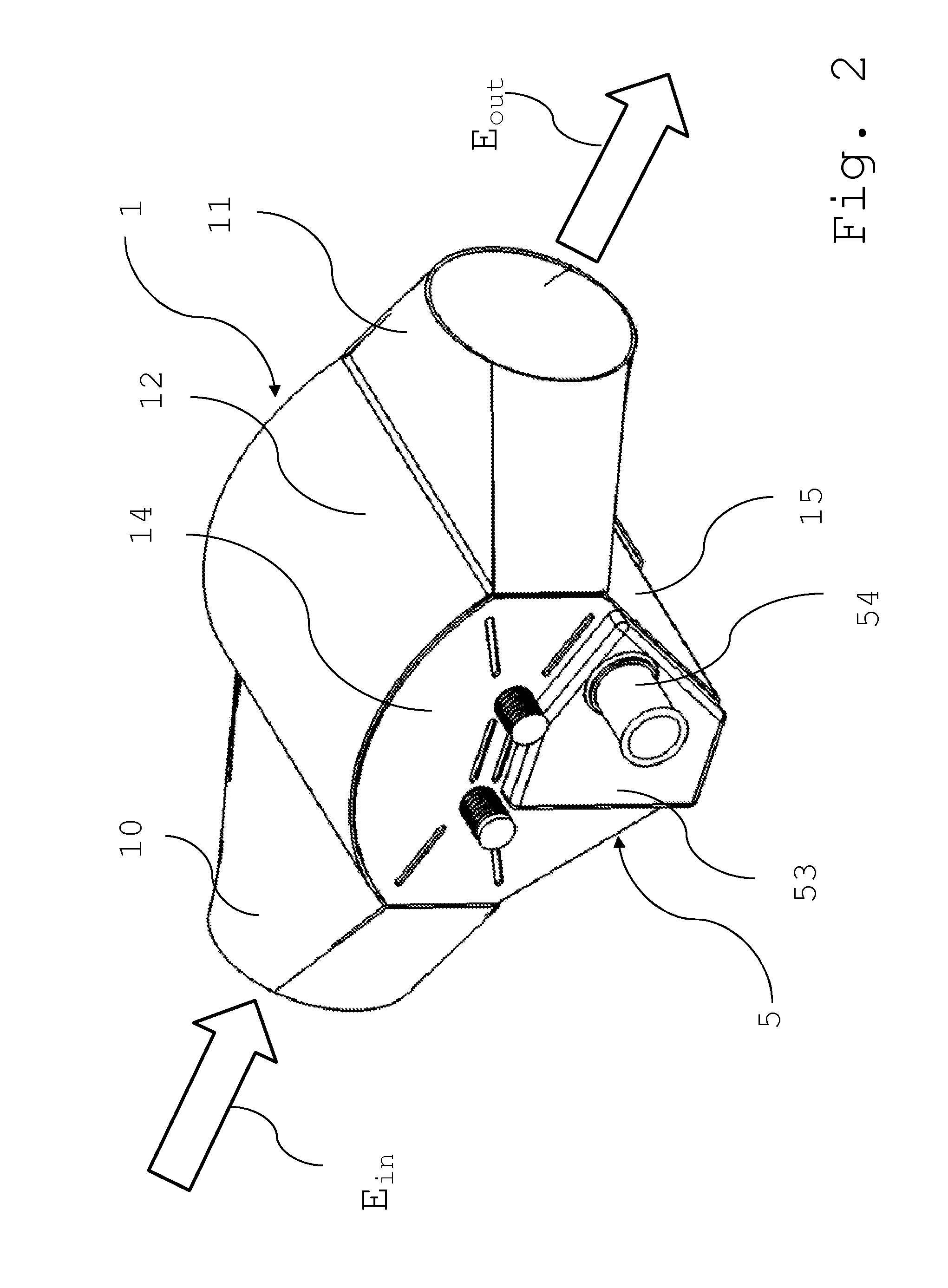
[0032]FIG. 1 and FIG. 2 are perspective views from opposite sides (front and rear views) of an embodiment of the unit according to the invention. As can be seen inflowing exhaust gas Ein coming from an internal combustion engine or from a catalytic converter arranged downstream of the engine enters the unit through an inlet 10 of a housing 1 of the unit, flows through the unit, and then exits from the unit as outflowing exhaust gas Eout through an outlet 11 of the housing. The housing 1 further comprises a top wall 12, two side walls 13 and 14, and a bottom 15. As can be seen from FIG. 1, an actuator 2 of the unit is coupled to a first axle 45 of a first valve flap 40 (see FIG. 3 or FIG. 4) and to a second axle 46 of a second valve flap 41 (see FIG. 3 or FIG. 4) with the aid of a mechanical link system 3. The unit further comprises a heat exchanger 5 the exchanger elements 52 of which (see FIG. 4) are arranged inside housing 1. An inlet 50 and a distribution manifold 51 of heat exch...
PUM
 Abstract
Description
Claims
Application Information