Vertical Takeoff and Landing ("VTOL") Aircraft

a vertical takeoff and landing technology, applied in vertical landing/take-off aircrafts, aircraft navigation control, canard-type aircraft, etc., can solve the problems of little to no cross-sectional area, inability to safely and efficiently taxi aircraft while in vertical position, and add instability to the landing, so as to maximize comfort, maximize comfort, and improve directional stability in flight

Active Publication Date: 2014-11-20
GALLIMORE IAN T MR
View PDF10 Cites 18 Cited by
  • Summary
  • Abstract
  • Description
  • Claims
  • Application Information

AI Technical Summary

Benefits of technology

[0036]It is also an object of the invention to provide an aircraft having a vertical tail. A traditional vertical tail may be included to improve directional stability in flight, and to prevent the aircraft from falling over backwards during the balance phase of a takeoff or landing event.
[0037]It is another object of the invention to provide an aircraft having a rotating pilot seat to orient the pilot in compatible positions during both horizontal flight and vertical takeoff and landing The pilot may be seated in a prone or near-prone position to maximize comfort during the VTOL phase of flight. The pilot seat may also rotate inside the aircraft. This would allow the pilot to takeoff or land in a comfortable forward leaning, upward position during the VTOL phase of flight, similar to the prone or near-prone position, and then to rotate using the seat into a more conventional aft-leaning, reclining position to maximize comfort during conventional cruise flight.
[0038]It is another object of the invention to provide a VTOL aircraft having full-time automatic control through multiply redundant control effectors that render negligible the is probability that the failure of one or more control effectors will result in a loss of aircraft control. This also allows the aircraft to be flown with or without a pilot.
[0039]It is an object of the invention to provide improved elements and arrangements thereof in an apparatus for the purposes described which is inexpensive, dependable and fully effective in accomplishing its intended purposes.

Problems solved by technology

A significant problem with tail-sitting aircraft is providing landing gear that are robust to potentially high sink-rate landings, while also being both lightweight and capable of being streamlined into the aft section of the aircraft, where little to no cross-sectional area is available for streamlining.
One skilled in the art would recognize the danger in retarding the descent without consideration of the thrust or the landing pad would add instability to the landing instead of facilitating landing.
A major problem that has prevented tail-sitting aircraft from being adopted more universally is the inability to taxi the craft safely and efficiently while in the vertical position.
Much of this difficulty derives from having three- or four-point landing gear that are relatively stiff even when they include spring-damper elements; and is considerably aggravated by gyroscopic forces for rotary-wing aircraft.
Even after being initially established aboard ship after touchdown, a sudden and / or sweeping movement by the ship deck can introduce forces and moments large enough to cause an aircraft to roll over.
Incidents and accidents are common in conditions of moderate to high ship motion.
In any case, accidents still occur.
The ability to balance and tilt relative to the flight deck, in particular relative to the high motion axis of the ship (typically the roll axis), reduces the potential for excessive torque on the landing gear that can create a violent dynamic rollover.
Several events could cause this event: 1) an excessively hard landing that causes the airplane to slip due to excessive force on the touchdown wheels; 2) fuel starvation that prevents thrust vectoring during the balance phase; 3) excessive environmental disturbances such as wind or turbulence; or 4) is excessive platform motion if landing on a moving platform.
Tail-sitting aircraft are uncomfortable for pilots to operate during the takeoff and landing phase when they are sitting in a position that is comfortable for cruising in horizontal flight.
This is primarily because they cannot easily see the landing area during the descent phase, but also because motion cues can be confusing when lying on one's back.
Aft-facing cameras could be pointed at the landing area during the descent; however, this is a less-than-optimal solution with current display technology, even if display symbols or other automation could compensate for the potentially confusing motion cues.
From this position the pilot can easily look down and around the aircraft, and motion cues are most natural; however, this does not yield the most useful position in horizontal flight.
As with the basic geometry of the aircraft, the seating and visibility configuration of a particular aircraft will result from a potentially large number of tradeoffs.
In any case, the ability to rotate the seat inside the aircraft requires a more upright position on average than provided by the prone position, which increases the frontal and surface area of the aircraft, ultimately increasing drag.
Manually controlling any aircraft in hover is notoriously difficult.
Furthermore, small tilt angles in a lift vector that is equal to the aircraft weight will create a downward vertical acceleration that will cause the aircraft to lose altitude.
During manual control, when using a reversible control system, it can be very difficult for the pilot to figure out how to manipulate the controls to manage acceleration, velocity, position, and attitude.
The best example of this difficulty is the amount of flight time pilots require to learn to hover a helicopter.
Stability and control augmentation systems comprising irreversible control systems have helped significantly with the hovering and transition flight tasks; however, challenges remain.
One key challenge is that with the control inputs used the pilot often has different functions or effects on the aircraft according to the phase of flight.
Pilots often report difficulty in adapting to these changes of function, and the most successful aircraft employ automatic flight control to assist in this transition.

Method used


Image

  • Vertical Takeoff and Landing ("VTOL") Aircraft
  • Vertical Takeoff and Landing ("VTOL") Aircraft
  • Vertical Takeoff and Landing ("VTOL") Aircraft

Examples


Embodiment Construction

)

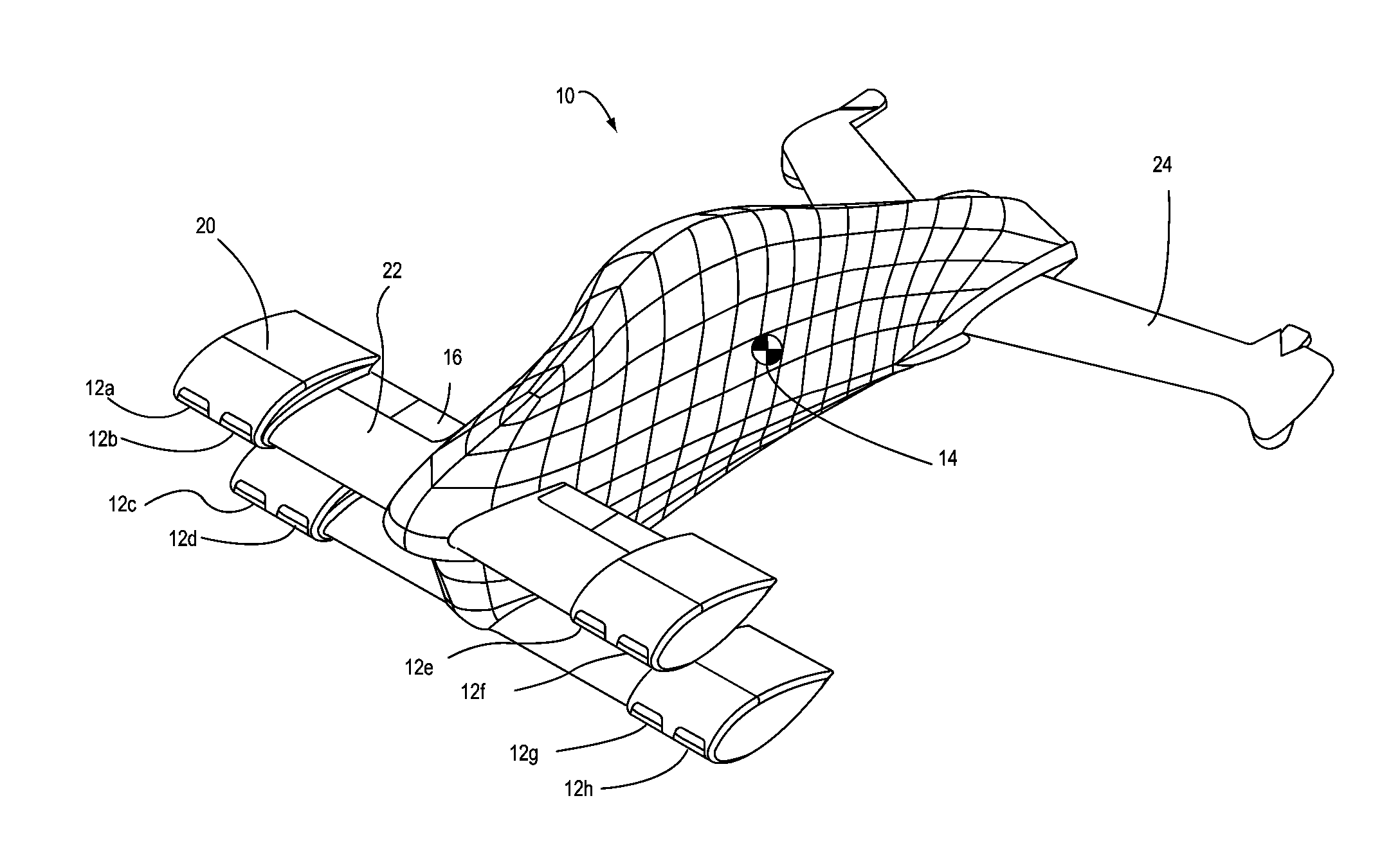
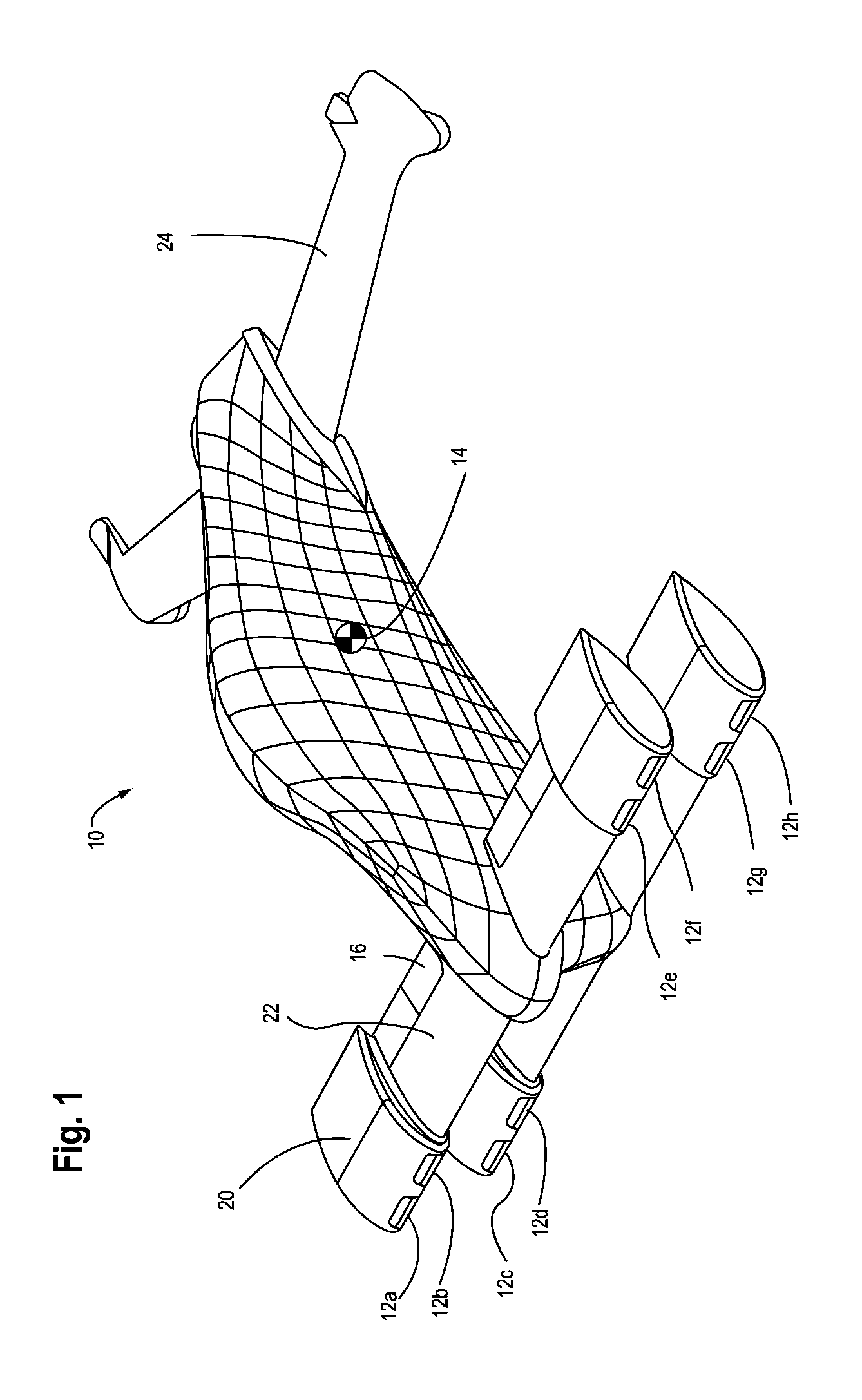
[0055]The preferred embodiment as shown in FIG. 1 is a tail-sitting aircraft 10 carrying at least one pilot. The aircraft can be flown without a pilot, or scaled up to larger size to carry more payload and passengers, given engines of sufficient thrust. The engines (12a-h) are mounted forward on the airplane so that the engine exhaust is as far as possible from the ground during takeoff and landing , among other objectives described hereunder. While eight engines are shown more engines or fewer engines may be used. When using turbines to generate thrust through the high-temperature combustion of fuel, this forward configuration minimizes the potential to burn the ground or nearby objects, which is a common problem with jet-powered VTOL aircraft. During near-hovering flight the normal position of the nozzles is such that exhaust is vectored away from the airplane, as will be described further hereunder. This exhaust direction also reduces the circulation of exhaust back up towards t...


PUM


Abstract

The invention is to an optionally piloted aircraft that can takeoff and land conventionally or vertically, and can convert between the two. The aircraft is immune to one or more engine failures during vertical flight through multiple engines and the use of a virtual nozzle. Aerodynamic controls are similarly redundant. Hovering flight is enabled with a novel stabilization system. Long range efficient cruise is achieved by turning off some engines in flight and sealing them into an aerodynamic fairing to achieve low drag. The resulting aircraft is capable of CTOL and VTOL, and is capable of converting between the two modes while in the air or on the ground. The aircraft can also be easily taxied on the ground in the conventional manner. Automatic controls considerably reduce the amount of training a pilot needs to fly and land the aircraft in either VTOL or CTOL mode.

Description

BACKGROUND OF THE INVENTION[0001]1. Field of the Invention[0002]The present application relates to aircraft that can take off and land vertically and aircraft that are capable of tail-sitting or be oriented parallel to the ground on “tricycle” wheels.[0003]2. Description of the Prior ArtOverview[0004]Aircraft that can take off and land vertically, and travel at high speeds for long distances, would have great utility for moving people and materials. However, to date few aircraft capable of Vertical Takeoff or Landing (“VTOL”) retain the ability to takeoff or land vertically following an engine failure, and no VTOL jet aircraft do so. A further significant problem with VTOL aircraft is the difficulty of maintaining precise control a) during the transition from horizontal to vertical flight and back, and b) during hover. These problems have prevented widespread commercial use of those VTOL aircraft, especially those that[0005]are capable of moderate to high-speed flight, such as tilt-...

Claims


Application Information

Patent Timeline
Patent Type & Authority Applications(United States)
IPC IPC(8): B64C29/00
CPCB64C29/0016B64C39/12B64C29/0066
Inventor GAILLIMORE, IAN TODDDRIVER, KENNETH DEAN
Owner GALLIMORE IAN T MR
Why Eureka
Try Eureka