Wireless proximity switch with a target device comprising an inverter

Active Publication Date: 2014-11-20
AMIN KAWA +1
View PDF4 Cites 2 Cited by
  • Summary
  • Abstract
  • Description
  • Claims
  • Application Information

AI Technical Summary

Benefits of technology

[0008]Since the inversion takes place in the target device the problems wit

Problems solved by technology

For example, proximity switches are often used in industrial and potentially dangerous environments for assisting in ensuring operational safety of a machine or an industrial process.
The proximity switch as described in SE520154 has been accepted as fulfilling the highest safety category requirements, but has a serious drawback in that the inversion is located in the swi

Method used


Image

  • Wireless proximity switch with a target device comprising an inverter
  • Wireless proximity switch with a target device comprising an inverter
  • Wireless proximity switch with a target device comprising an inverter

Examples


Example

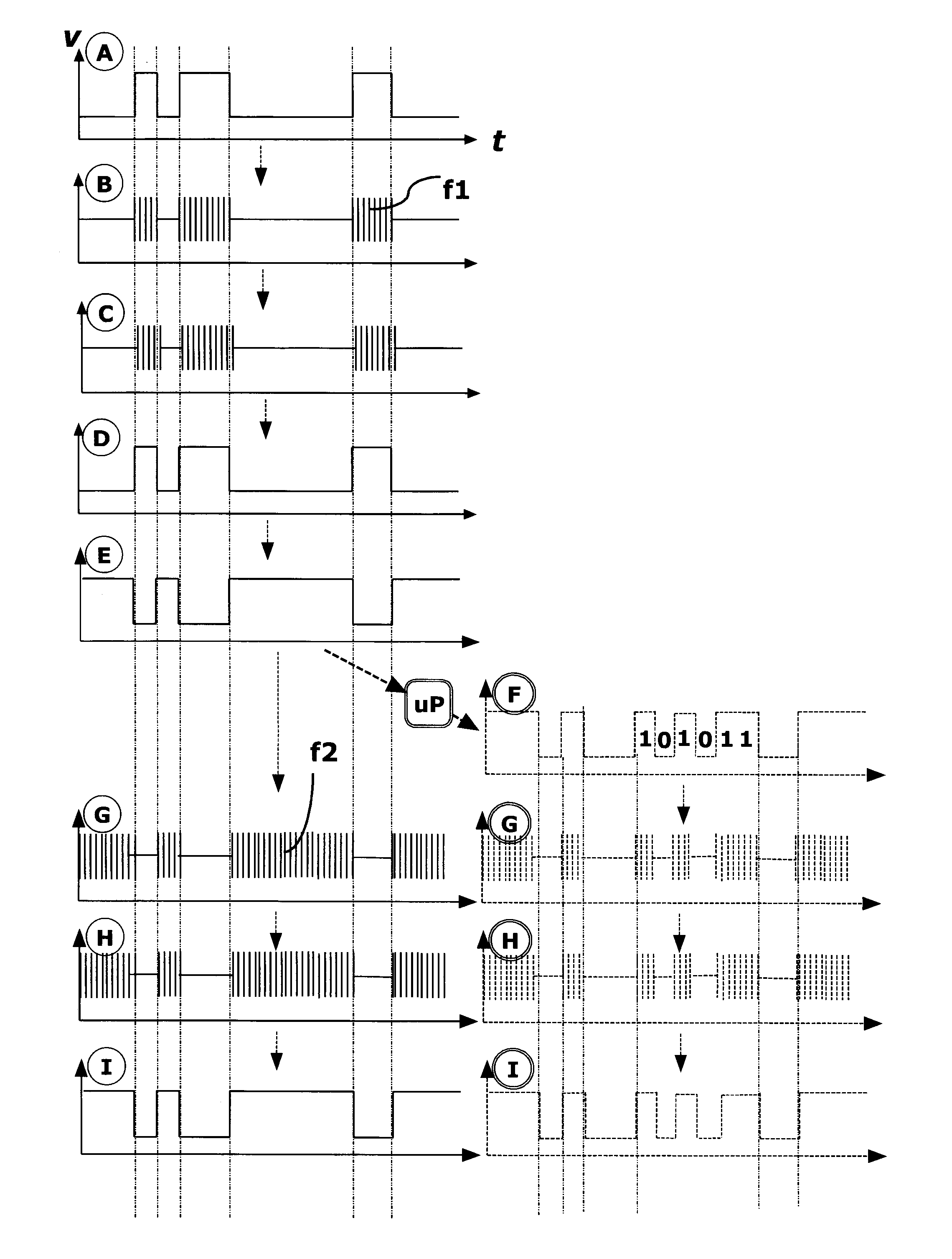
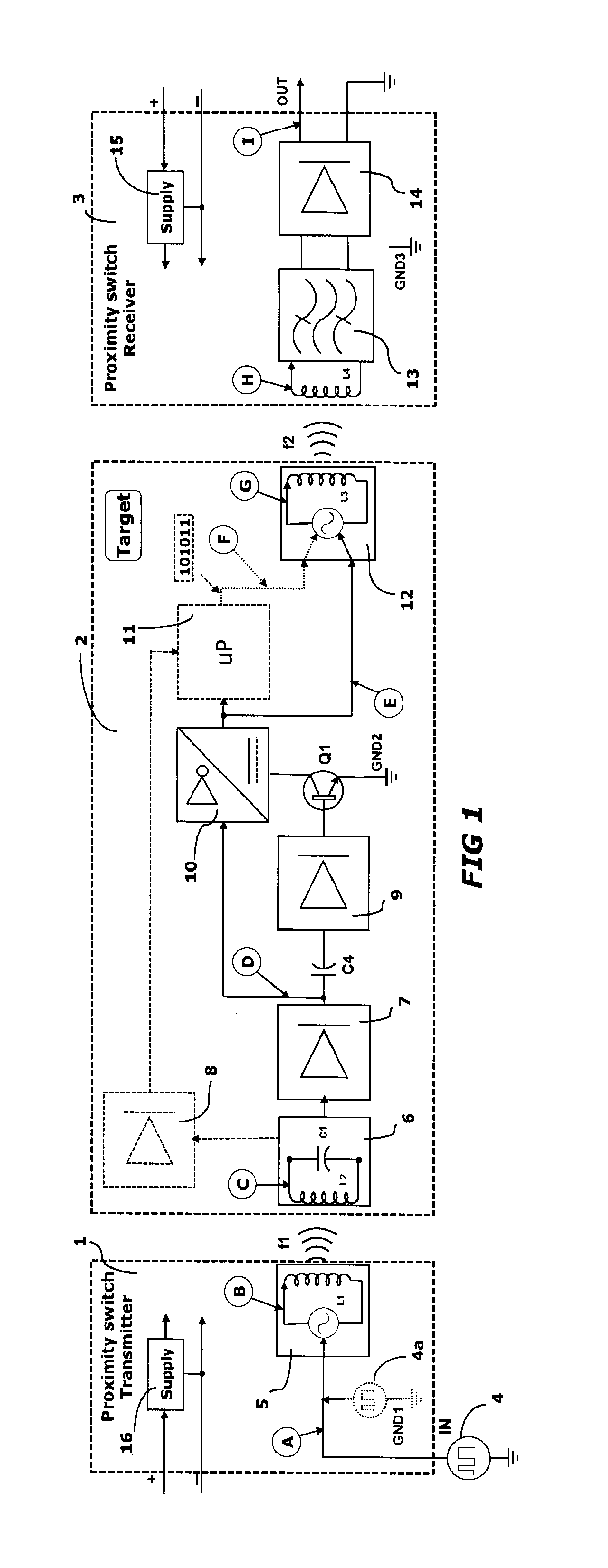
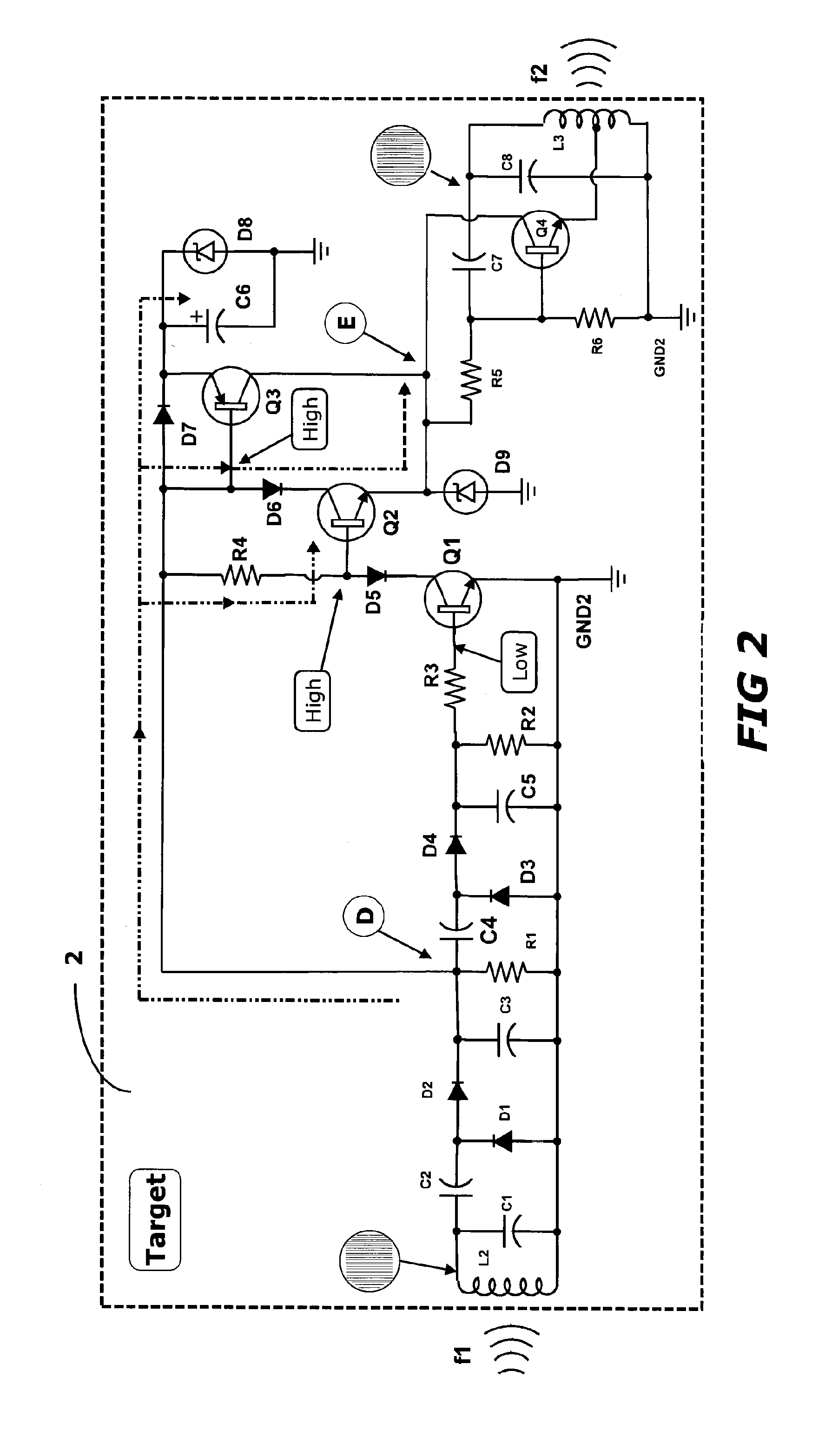
[0019]FIG. 1 is intended to illustrate the basic function of a target device 2 for use with a switch unit 1, 3 in a safe proximity switch according to the invention. The proximity switch makes use of dynamic signals, and inversion of the dynamic signal in the proximity switch, which implies that this switch is categorized as a safe proximity switch.

[0020]A proximity switch is used to wirelessly detect whether a moving object is present within a predetermined distance of a proximity switch or not. In order to achieve this, the movable object (which may be a door, window, gate, hatch, etc) is provided with a target, which does not have to be electrically connected to a power supply.

[0021]A preferred embodiment of the invention (target device 2) together with the switch unit 1, 3 is schematically illustrated in FIG. 1. The proximity switch is electrically connected to one / two external power sources 15 and 16 via a pair of poles (+ and −) for direct current. -Here, two different supply ...


PUM


Abstract

A target device for use with a switch device of a proximity switch has a wireless receiver means (6) for detecting and receiving a first pulsating signal (A) with a first carrier frequency (f1) from a nearby transmitter module (5), demodulating (6, 7) the received signal, and if a superimposed digital signal is present, inverting (9, 10, C4, and Q1) the superimposed received digital signal or, if the superimposed digital signal is absent, passing the existing energy through (10). The target device also has a wireless transmitter means (12) for modulating and sending the inverted pulse train if this exists by the second carrier frequency (f2) to the receiver switch unit (13). Additionally, the target comprises functionality to transmit the carrier frequency (f2) continuous and unmodulated where a continuous and unmodulated carrier frequency (f1) is present. However, upon existence of the pulsating signal only one of the receiver (6) and the transmitter (12) receives or transmits a signal at a given time.

Description

TECHNICAL FIELD[0001]The present invention relates to a target device for use with a switch device of a proximity switch. The target device is arranged to detect and receive a superimposed carrier frequency. The carrier frequency is demodulated and if a superimposed digital signal is present, the superimposed received digital signal is inverted and then the inverted digital signal is with a carrier frequency and is transmitted to a receiver unit of the switch device in the same proximity switch or to a receiver in another proximity switch. The invention also concerns a solution to this inverting, so that the inverting takes place without delay, and the option to add a device so that the target device is assigned its individual code.BACKGROUND[0002]Proximity switch (for example as described in SE520154 which is a type of inductive proximity switch) are used in different applications to detect the presence or absence of a second object in relation to a first object. For this purpose, ...

Claims


Application Information

Patent Timeline
IPC IPC(8): H03K17/95
CPCH03K17/9537G01S13/758G01S13/767H03K17/954H03K2217/958
Inventor AMIN, KAWA
Owner AMIN KAWA
Why Eureka
Try Eureka