Modular ladar sensor

a module-based, ladar-based technology, applied in the direction of distance measurement, instruments, surveying and navigation, etc., can solve the problems of actors, sets, athletes, or objects in play,

Active Publication Date: 2014-11-20
CONTINENTAL AUTONOMOUS MOBILITY US LLC
View PDF3 Cites 91 Cited by
  • Summary
  • Abstract
  • Description
  • Claims
  • Application Information

AI Technical Summary

Benefits of technology

[0007]A modular ladar sensor employs a receiver module within housing. The housing incorporates a quick connect optical receptacle coupler and has a laser transmitter electrical connector and a laser transmitter mechanical mount for rapidly mounting a laser transmitter module. A lens assembly with a quick connect optical plug coupler mates with the optical receptacle coupler. A laser transmitter module with an electrical connector is adapted to engage and mate with the laser transmitter electrical connector, and with complementary mechanical mounting and fastening features mates with the laser transmitter mechanical mount. The laser transmitter has a modulated laser light output and a diffusing optic for illuminating a scene in the field of view of the modular ladar sensor. A two dimensional array of light sensitive detectors is p

Problems solved by technology

Stereo systems, holographic capture systems, and those which acquire shape from motion, have all been proposed and in some cases demonstrated, but what is lacking is a system with the capabilit

Method used


Image

  • Modular ladar sensor
  • Modular ladar sensor
  • Modular ladar sensor

Examples


Embodiment Construction

[0024]This application contains new subject matter related to previous U.S. Pat. Nos. 5,696,577, 6,133,989, 5,629,524, 6,414,746, 6,362,482, D463,383, and U.S. patent application Ser. No. 10 / 066,340 filed on Jan. 31, 2002 and published as US 2002 / 0117340 A1, the disclosures of which are incorporated herein by reference.

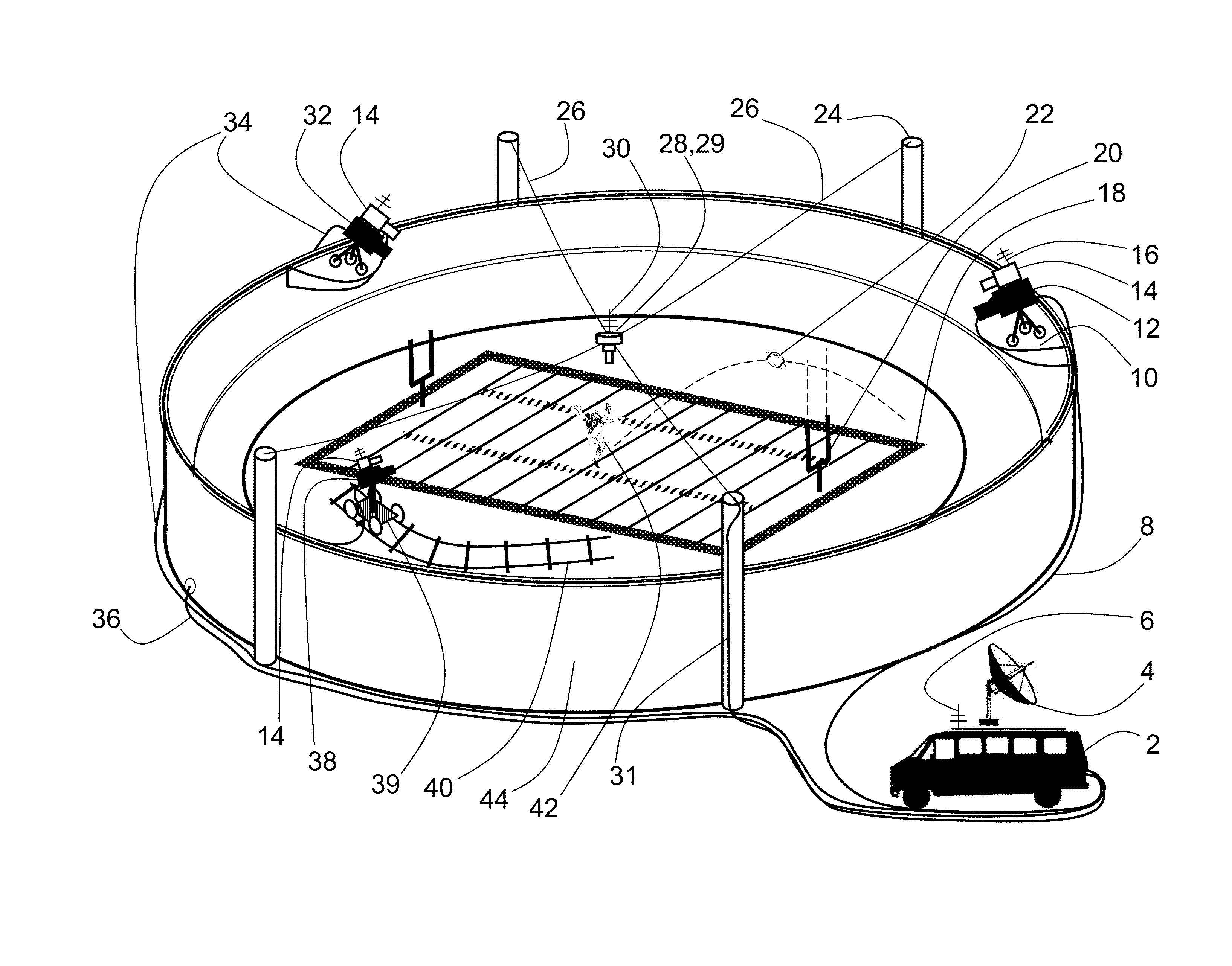
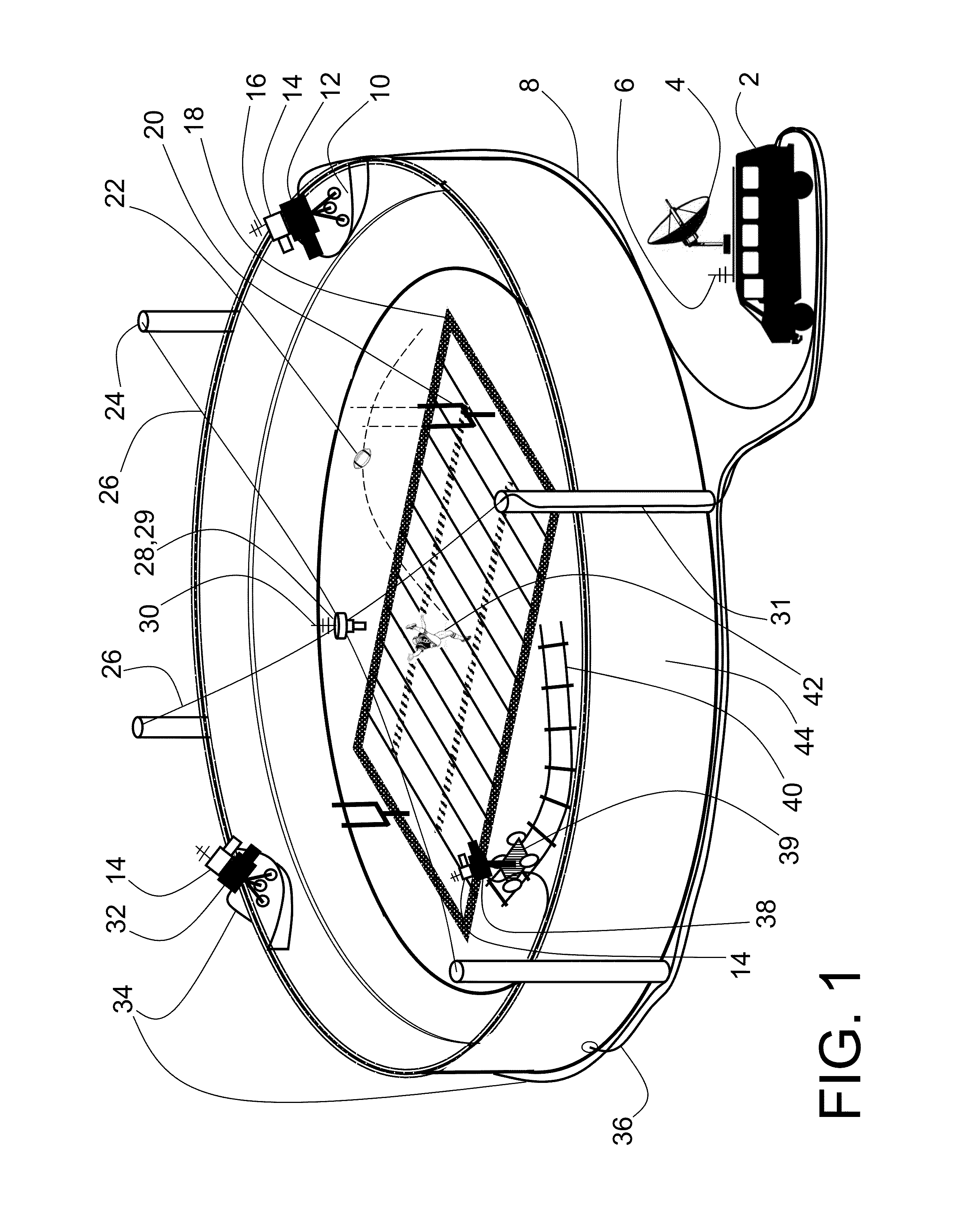
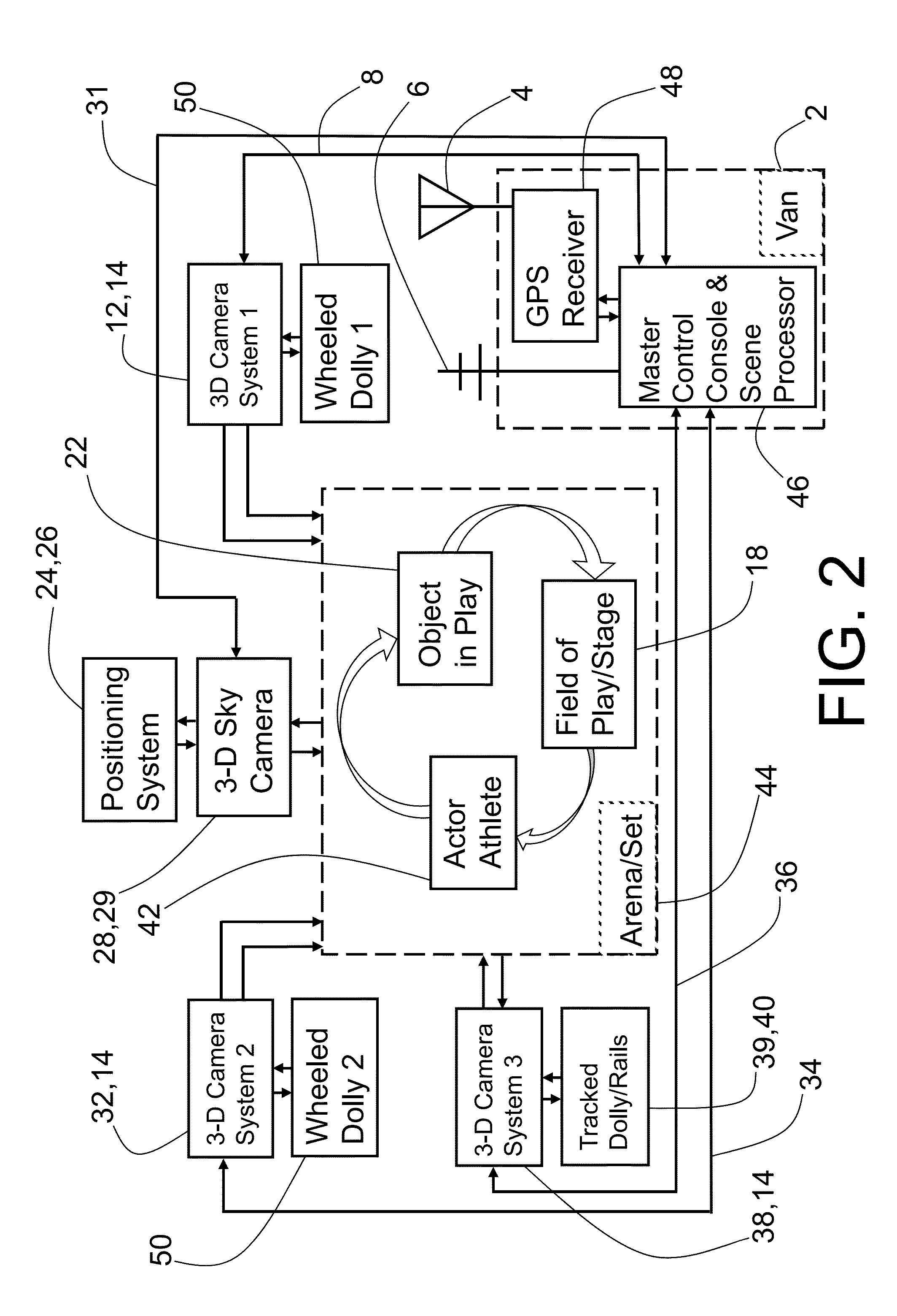
[0025]The embodiments disclosed herein provide a device for 3-D imaging using a modular ladar sensor with a field of view and a wavelength of operation comprised of several components, wherein each of the key components of the ladar sensor is a self contained sub-assembly, easily assembled together to produce a functional ladar sensor. Each of the modules, or sub-assemblies, has both mechanical and electrical interfaces well suited to modular assembly. The modular ladar sensor may also have an optical interface and connector. The modular ladar sensor is well adapted externally to be rapidly mounted to any equipment having a proper set of external mechanical, electrica...


PUM


Abstract

A lightweight, low volume, inexpensive LADAR sensor incorporating 3-D focal plane arrays is adapted specifically for modular manufacture and rapid field configurability and provisioning. The present invention generates, at high speed, 3-D image maps and object data at short to medium ranges. The techniques and structures described may be used to extend the range of long range systems as well, though the focus is on compact, short to medium range ladar sensors suitable for use in multi-sensor television production systems and 3-D graphics capture and moviemaking. 3-D focal plane arrays are used in a variety of physical configurations to provide useful new capabilities.

Description

BACKGROUND[0001]1. Field[0002]The embodiments disclosed herein relate generally to 3-D image generation and recording and more particularly to systems which may synthesize 3-D solid object models from data supplied by multiple optical sensors. Many systems have been proposed to meet the challenge of using video cameras in a production system to create 3-D maps of scenes and models of solid objects. Stereo systems, holographic capture systems, and those which acquire shape from motion, have all been proposed and in some cases demonstrated, but what is lacking is a system with the capability of producing a full 360 degree solid object model without a time consuming set up, and operating conditions which result in restrictions on the actors, set, scene, athlete, or object in play.[0003]2. References to Related Art[0004]The 3-D imaging technology disclosed in Stettner et al, U.S. Pat. Nos. 5,446,529, 6,133,989 and 6,414,746 provides with a single pulse of light, typically pulsed laser l...

Claims


Application Information

Patent Timeline
IPC IPC(8): H04N13/02G01S17/89H04N13/00G01S7/486G01S7/4863G01S17/87G01S17/894G01S17/931
CPCH04N13/025G01S7/4863H04N13/0062H04N13/0051G01S17/89G01S7/4813H04N13/167H04N13/172H04N13/25G01S17/931G01S17/894G01S17/87
Inventor GILLILAND, PATRICKHEUGHEBAERT, LAURENTSPAGNOLIA, JOSEPHSHORT, BRADSTETTNER, ROGER
Owner CONTINENTAL AUTONOMOUS MOBILITY US LLC
Why Eureka
Try Eureka