Shock resistant bearing for a timepiece

a technology of shock-resistant bearings and timepieces, which is applied in the field of shock-resistant bearings, can solve the problems of high manufacturing cost of shock-resistant bearings according to the teaching of the above patent, the bottom of a four-sided hole is not optimal for supporting a pivot, and the technique requires complex expensive plants which are different, so as to improve the centrifugal force of the axis, minimise friction, and improve the effect of quality

Active Publication Date: 2014-11-20
THE SWATCH GRP RES & DEVELONMENT LTD
View PDF9 Cites 6 Cited by
  • Summary
  • Abstract
  • Description
  • Claims
  • Application Information

AI Technical Summary

Benefits of technology

[0012]The manufacturing method according to the invention makes it possible to obtain a high quality transparent shock resistant bearing by a relatively inexpensive method which only requires machining in chemical baths. Further, this method makes it possible to machine a blind hole for the bearing whose bottom is at least partially defined by a trigonal pyramid against whose faces the pivot of a rotating wheel set abuts. This blind hole ensures improved centring of the axis of the rotating wheel set and also minimises friction. A transparent bearing also has a technical advantage in that it makes it easier to check the presence of oil in the hole.

Problems solved by technology

First of all, it will be noted that the bottom of a four-sided hole is not optimum for supporting a pivot.
This latter technique requires complex expensive plants which are different from those used for anisotropic wet chemical etching.
Thus, the manufacturing cost of shock resistant bearings according to the teaching of the above Patent is relatively high.
Indeed, the orientation of the silicon substrate required to obtain the flared pyramid-shaped hole cannot provide an elastic structure with arms having substantially vertical lateral walls, or the peripheral annular portion.
Further, to obtain apertures in a single crystal silicon wafer with vertical walls, only specific silicon crystal orientations in the wafer are possible (incompatible with the orientation for obtaining pyramid-shaped holes).
The possible directions for such vertical walls are limited and the vertical walls are only formed of plane surfaces.
As regards silicon, as mentioned above, although it is possible to obtain slots or apertures with vertical walls, designs are limited.
In particular, it is not possible to obtain all the designs shown in the Figures of the above Patent document by chemical etching of a silicon crystal wafer.
It will be noted that the flat bottomed cylindrical shape is not optimum since the pivot moves and rubs against the cylindrical portion in an erratic manner, because the hole is wider than the portion of the pivot introduced therein.

Method used


Image

  • Shock resistant bearing for a timepiece
  • Shock resistant bearing for a timepiece
  • Shock resistant bearing for a timepiece

Examples


Embodiment Construction

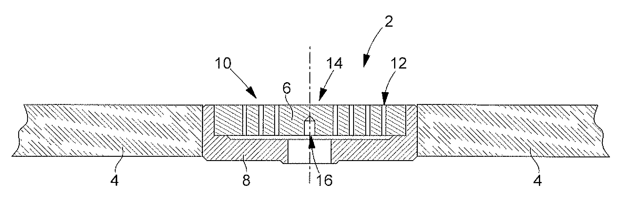
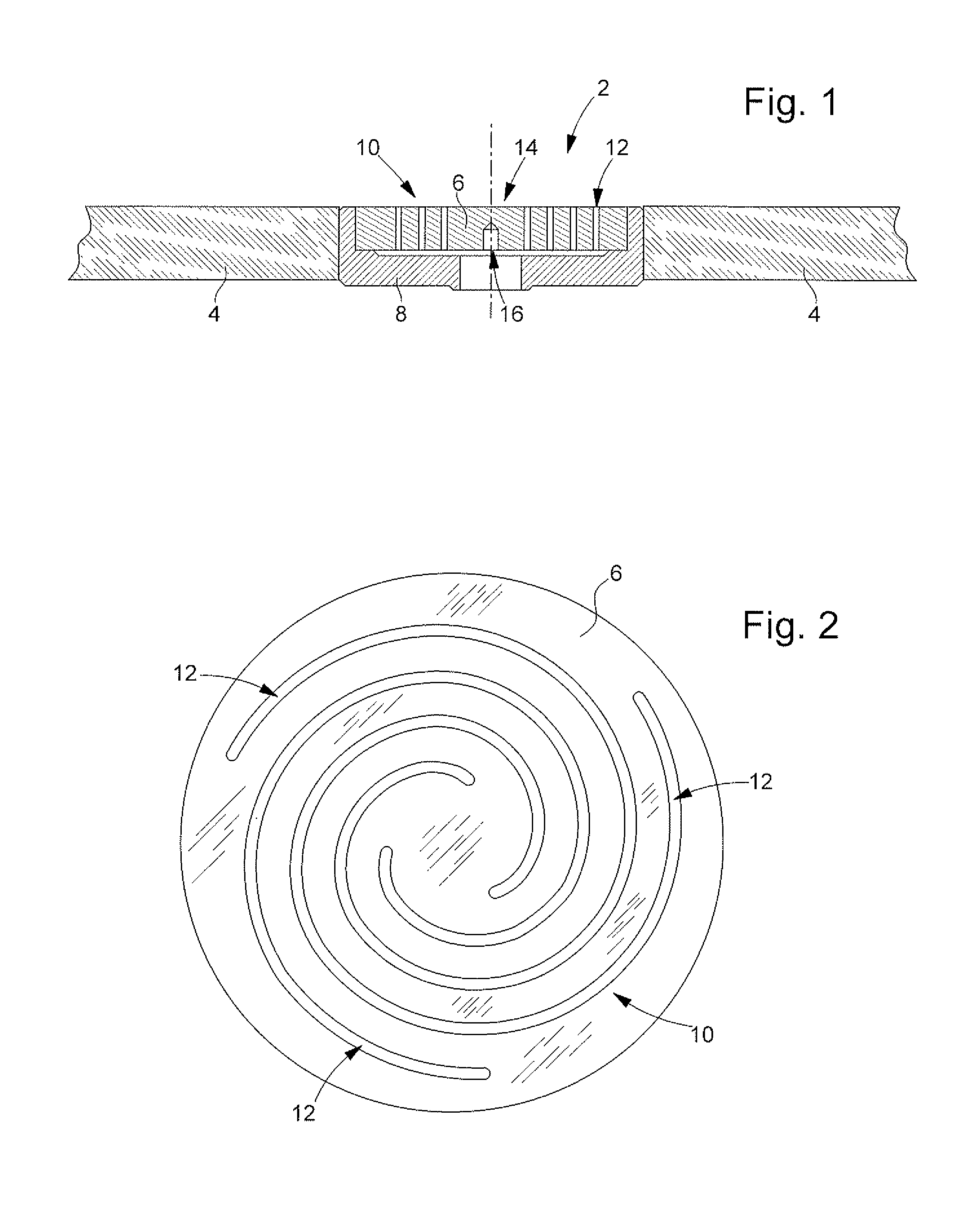
[0024]A shock resistant bearing 2 according to the invention will be described below with reference to FIGS. 1, 2, 3 and 5. This shock resistant bearing is arranged in a bridge or a plate 4 of a timepiece and is formed of a single crystal quartz wafer 6 (the wafer defining a disc or a circular plate) and of a base 8 which has a housing for wafer 6. This wafer includes an elastic structure 10, formed by the substantially circular slots 12 machined in the wafer, and a central portion 14 carried by this elastic structure and having a blind hole 16 intended to receive a pivot of a rotating wheel set (not shown) of the timepiece movement. The slots, substantially shaped in an arc of a circle, define between them elastic spiral arms connecting the central portion to the peripheral area of wafer 6. This elastic structure and the central portion are thus formed by one single-piece part formed of single crystal quartz.

[0025]As a result of the arrangement of an elastic structure at the periph...


PUM

PropertyMeasurementUnit
angleaaaaaaaaaa
angleaaaaaaaaaa
diameteraaaaaaaaaa

Abstract

Shock resistant bearing for a timepiece including an elastic structure and a central portion carried by the elastic structure, the central portion having a blind hole intended to receive a pivot of a rotating wheel set of the timepiece. The elastic structure and the central portion are formed by a single-piece part formed of single crystal quartz and the blind hole has at least partially the shape of a truncated or non-truncated trigonal pyramid against which the end of the pivot abuts. The invention also concerns a method of manufacturing a shock resistant bearing of this type wherein the single-piece wafer is machined in an anisotropic etching bath for single crystal quartz. Preferably, two masks are respectively arranged on the two sides of the wafer to simultaneously etch the quartz from both sides.

Description

FIELD OF THE INVENTION [0001]The present invention concerns the field of shock resistant bearings (bearings with a shock absorber device) for a timepiece and the methods of manufacturing the same. In particular, the invention concerns a shock resistant bearing intended to receive a pivot of the balance staff of a mechanical watch movement.BACKGROUND OF THE INVENTION[0002]CH Patent 700496 describes a shock resistant bearing formed by single crystal silicon and including a central portion and radial elastic arms connecting this central portion to a peripheral annular portion. The central portion includes a flared hole having the shape of a four-sided pyramid. First of all, it will be noted that the bottom of a four-sided hole is not optimum for supporting a pivot. As regards the making of a hole of this type, the above Patent provides anisotropic wet chemical etching. To achieve this, it is mentioned that the silicon substrate must be oriented properly to enable machining of the pyram...

Claims


Application Information

Patent Timeline
Patent Type & Authority Applications(United States)
IPC IPC(8): G04B31/004G04B31/06G04B31/02
CPCG04B31/004G04B31/06G04B31/02
Inventor HESSLER, THIERRY
Owner THE SWATCH GRP RES & DEVELONMENT LTD
Why Eureka
Try Eureka