
Device for measuring a pressure and a temperature of a fluid medium flowing in a duct

Active Publication Date: 2014-11-20
ROBERT BOSCH GMBH
View PDF13 Cites 38 Cited by
  • Summary
  • Abstract
  • Description
  • Claims
  • Application Information

AI Technical Summary

Benefits of technology

The present invention is a device that measures the pressure and temperature of a fluid flowing in a duct. The device is advantageous in that it allows for easy mounting of the pressure sensor and temperature sensor without the need for a separate holder. The positioning of the carrier substrate in the connecting piece also improves the durability of the temperature sensor, reducing the risk of damage. The device may be modularly assembled, saving engineering and manufacturing costs, and its components are protected from damage by a passivating layer. The technical effects of this invention are improved space-saving, durability, and protection against corrosion attacks.

Problems solved by technology

In operation, such devices are subjected to a variety of thermal and mechanical loads.
In such a device, high flow velocities may disadvantageously cause vibrations to be excited in the temperature sensor, in which case the entire conducting wire is set into vibration.
In this manner, considerable engineering and manufacturing costs for different variants of the device may be saved.

Method used


Image

  • Device for measuring a pressure and a temperature of a fluid medium flowing in a duct
  • Device for measuring a pressure and a temperature of a fluid medium flowing in a duct
  • Device for measuring a pressure and a temperature of a fluid medium flowing in a duct

Examples


Embodiment Construction

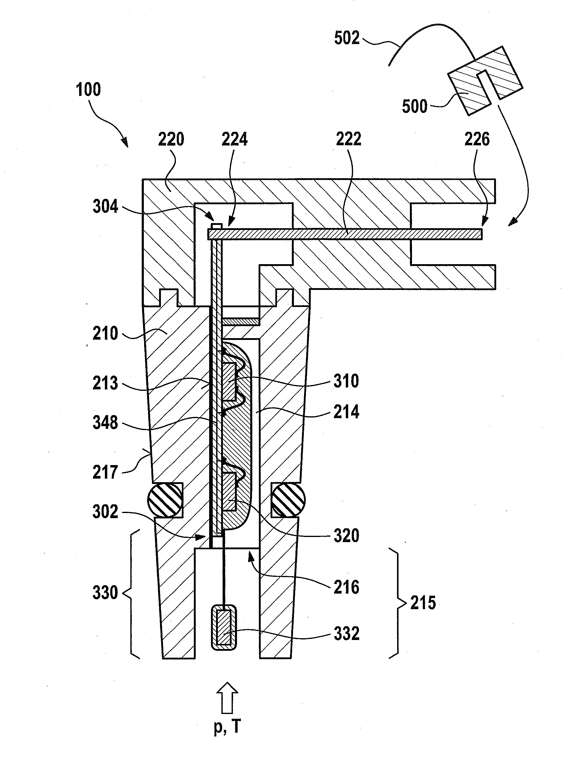
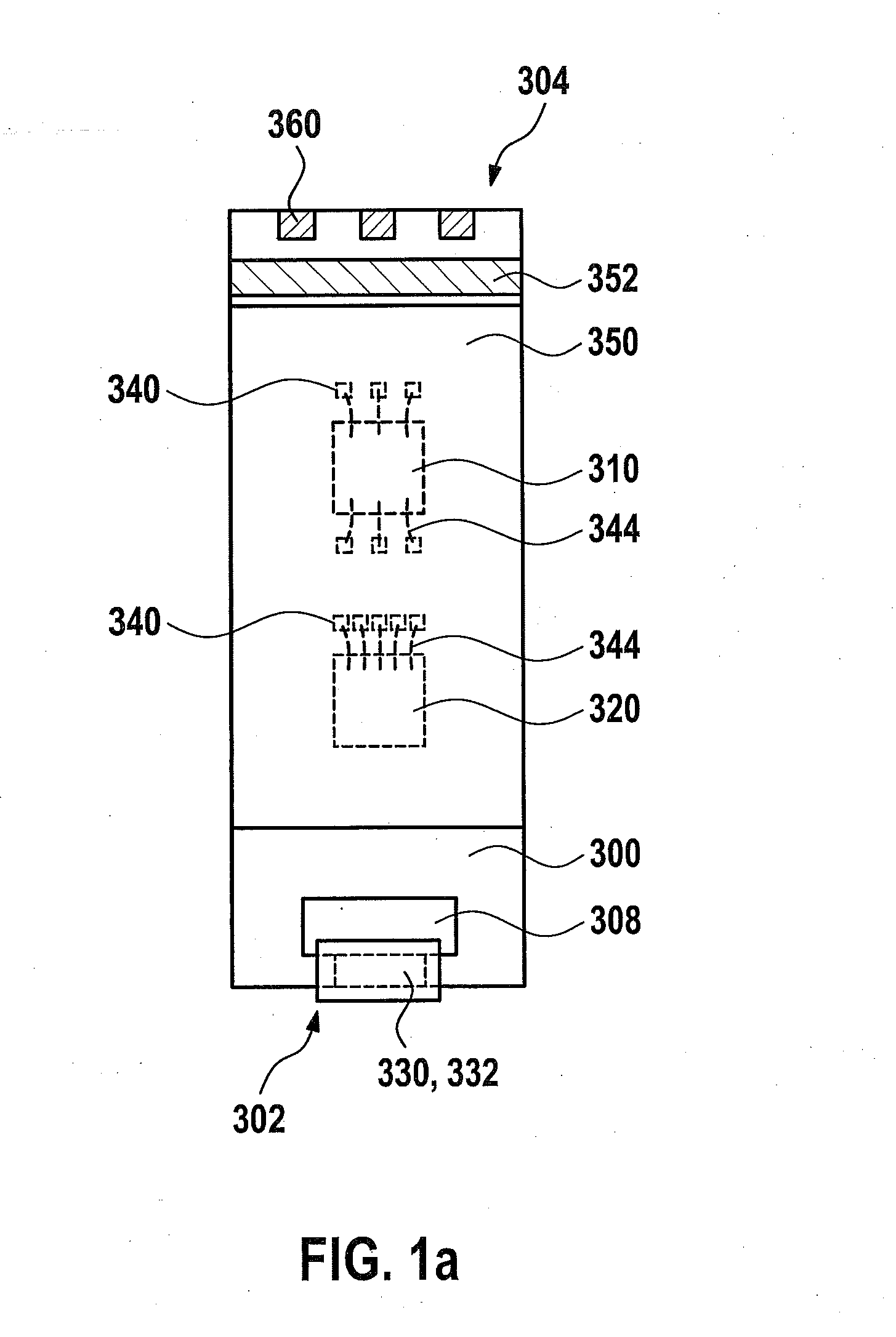
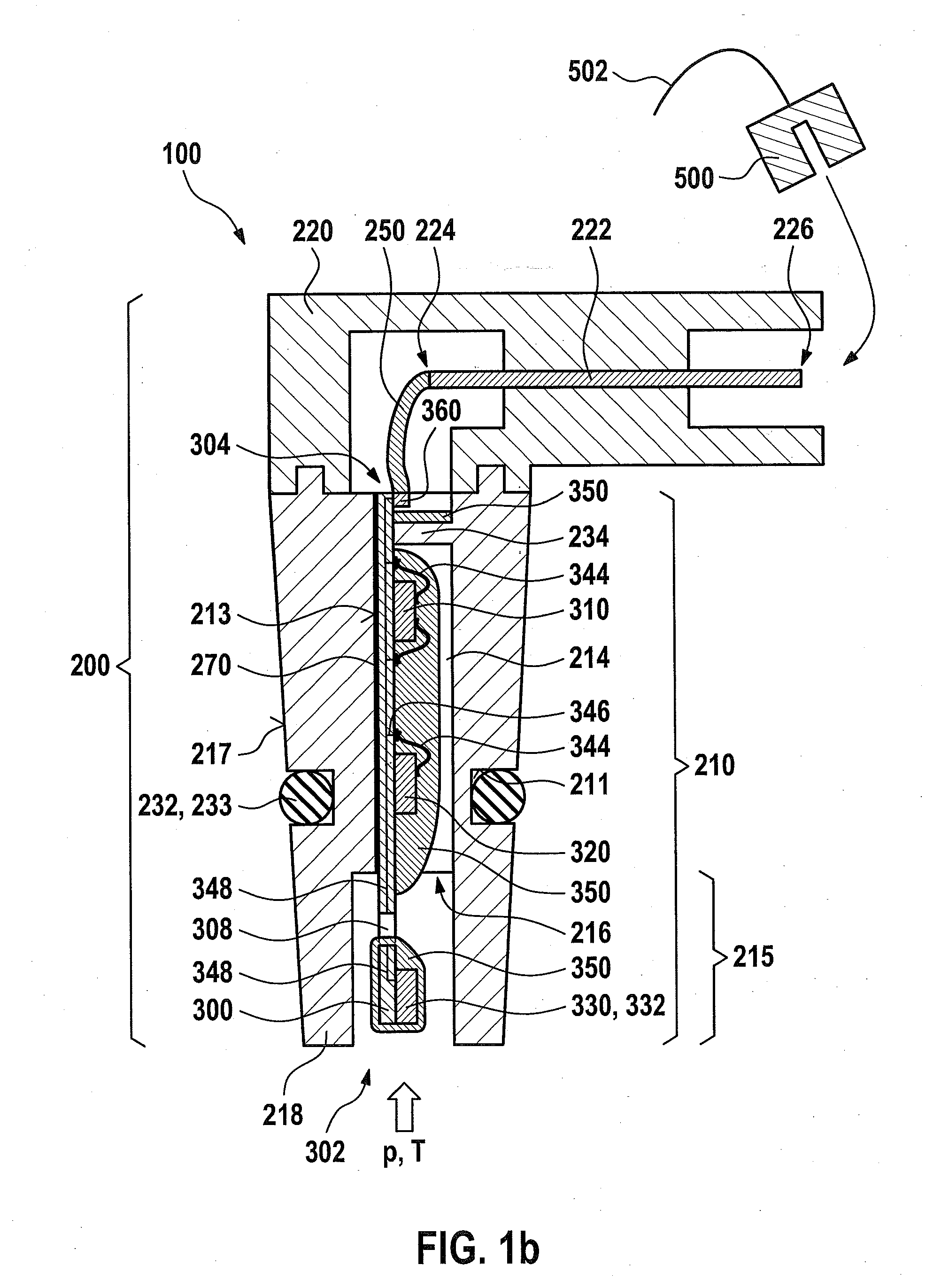
[0021]FIG. 1a shows a carrier substrate 300 for attachment in an interior chamber 214 of a connecting piece 210 of a first exemplary embodiment of a first specific embodiment of a device 100 for measuring a pressure (p) and a temperature (T) of a fluid medium flowing in a duct, illustrated in FIG. 1b. Carrier substrate 300 preferably takes the form of a printed circuit board (PCB), a flexible circuit board or a ceramic. It is particularly preferred that a carrier substrate 300 taking the form of a circuit board be made of a circuit board material FR4 or better.

[0022]An integrated circuit 310, for example, an application-specific integrated circuit (ASIC), is positioned on carrier substrate 300. Integrated circuit 310 is electrically contacted with contacting elements 340, e.g., bonding pads, of carrier substrate 300, with the aid of electrical connecting elements 344, e.g., with the aid of bonding wires. Additionally situated on carrier substrate 300 is a pressure sensor element 320...


PUM


Abstract

A device for measuring a pressure and a temperature of a fluid medium flowing in a duct, the device including a pressure sensor element; a temperature sensor having a temperature sensor element; a housing that has a connecting piece, the connecting piece being insertable into the duct in an insertion direction, the connecting piece having an interior chamber, the interior chamber having an opening through which the interior chamber may be exposed to the fluid medium; and a carrier substrate, the pressure sensor element being connected electrically and mechanically to the carrier substrate. In order to increase the service life of the temperature sensor, and in order to allow temperature measurement that is as accurate as possible, it is provided, in this context, that the carrier substrate be positioned substantially parallel to the insertion direction in the interior chamber of the connecting piece, the interior chamber extending along the insertion direction, and it is provided that the temperature sensor be connected electrically and mechanically to the carrier substrate.

Description

FIELD OF THE INVENTION[0001]The present invention relates to a device for measuring a pressure and a temperature of a fluid medium flowing in a duct, for example, in the induction pipe of an internal combustion engine.BACKGROUND INFORMATION[0002]A device for measuring a pressure and a temperature in the induction pipe of an internal combustion engine is known from German Published Patent Appln. No. 197 31 420. This device has a connecting piece insertable into the induction pipe. A temperature sensor used for measuring the temperature is inserted into this connecting piece. The temperature sensor is made up of a temperature sensor element and of lead wires, which are guided into the interior of the device, and there, electrically contacted and mechanically held.[0003]In operation, such devices are subjected to a variety of thermal and mechanical loads. The temperature sensor has a temperature sensor element, which is attached to a conducting wire and is exposed to a flow of a fluid ...

Claims


Application Information

Patent Timeline
IPC IPC(8): G01K13/02G01L11/00G01K1/14
CPCG01L11/00G01K13/02G01K2205/02G01L19/0084G01L19/0092G01L19/0627G01L19/143G01L23/24H01L2224/48091H01L2924/00014
Inventor KAISER, RALFLUX, ALEXANDERREINHARD, MARKUSGMELIN, CHRISTOPHHERRMANN, REINHOLDPATZNER, PATRICK
Owner ROBERT BOSCH GMBH
Features
  • Generate Ideas
  • Intellectual Property
  • Life Sciences
  • Materials
  • Tech Scout
  • Unparalleled Data Quality
  • Higher Quality Content
  • 60% Fewer Hallucinations
Learn More