Super-resolution formation fluid imaging with contrast fluids

a formation fluid and super-resolution technology, applied in the field of subsurface structures imaging, can solve the problems of low frequency operating range, large brines, and high frequency operating range required for continuous-wave electromagnetic surveys

Active Publication Date: 2014-11-27
SAUDI ARABIAN OIL CO
View PDF2 Cites 30 Cited by
  • Summary
  • Abstract
  • Description
  • Claims
  • Application Information

AI Technical Summary

Benefits of technology

[0008]Briefly, the present invention provides a new and improved method of electromagnetic imaging of formation of a subsurface hydrocarbon reservoir structure containing fluids. An injection fluid containing particles to change the electromagnetic character of the reservoir where fluids are present is introduced into the reservoir structure. Pulses of electromagnetic energy signals are emitted to travel through the reservoir. Waveforms of the emitted electromagnetic energy signals ...

Problems solved by technology

The presence of brine, as well as the large inter-well distances on the order of 1 kilometer or more, and thermal noise limits in conventional receivers caused continuous-wave EM surveys to require very low frequency operation, usually about 200 Hz.
The low frequency operating range which was required severely limite...

Method used


Image

  • Super-resolution formation fluid imaging with contrast fluids
  • Super-resolution formation fluid imaging with contrast fluids
  • Super-resolution formation fluid imaging with contrast fluids

Examples


Embodiment Construction

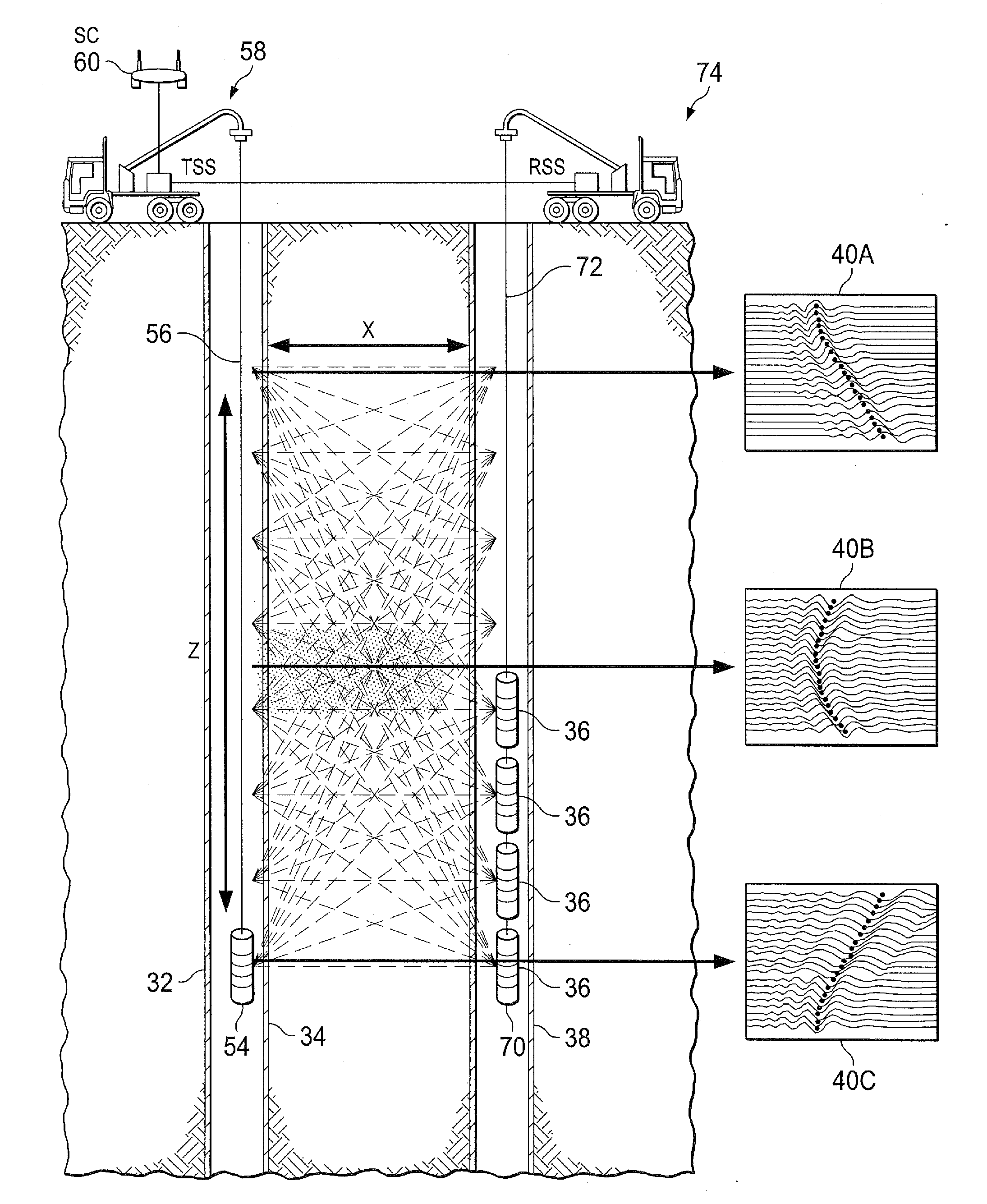
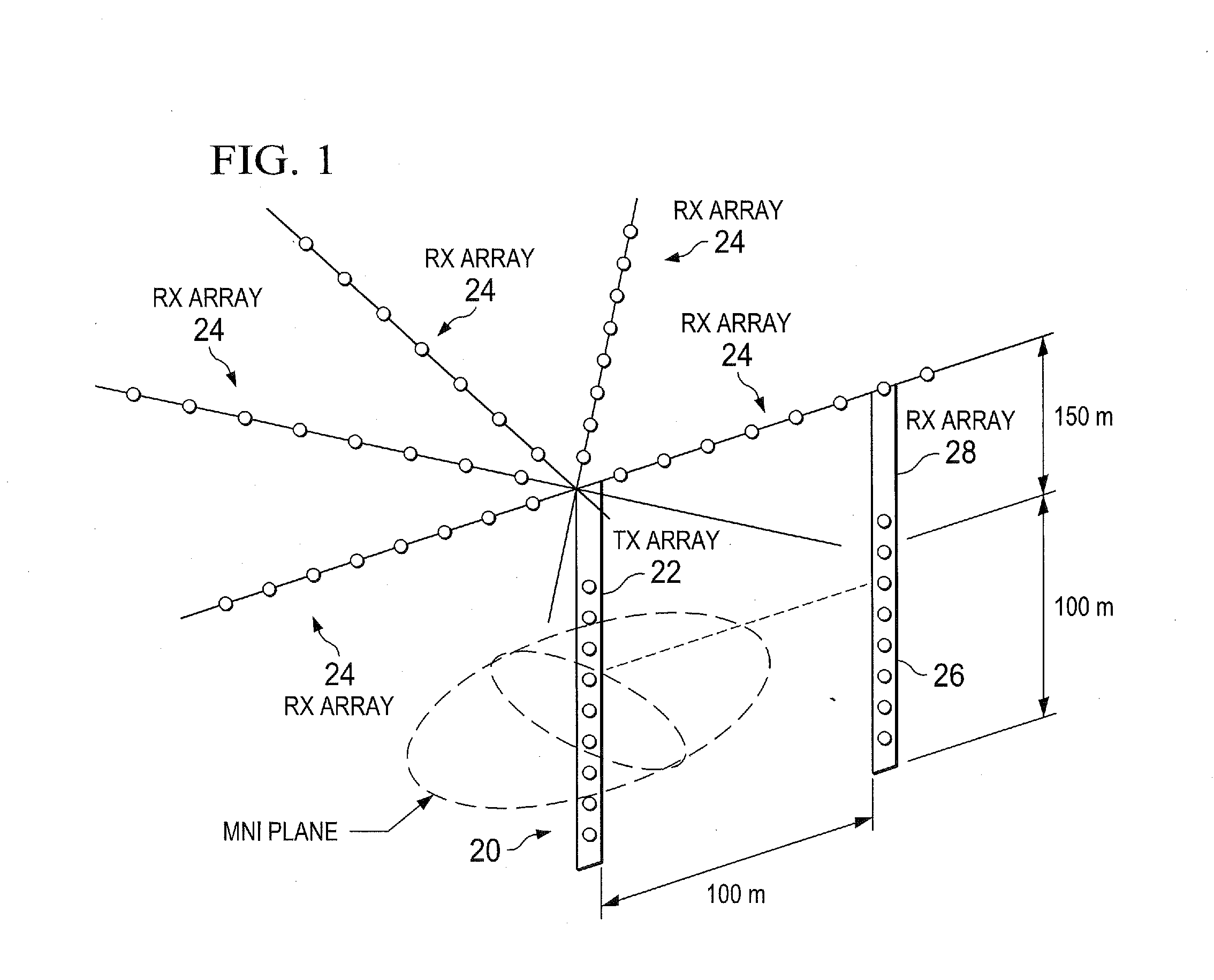
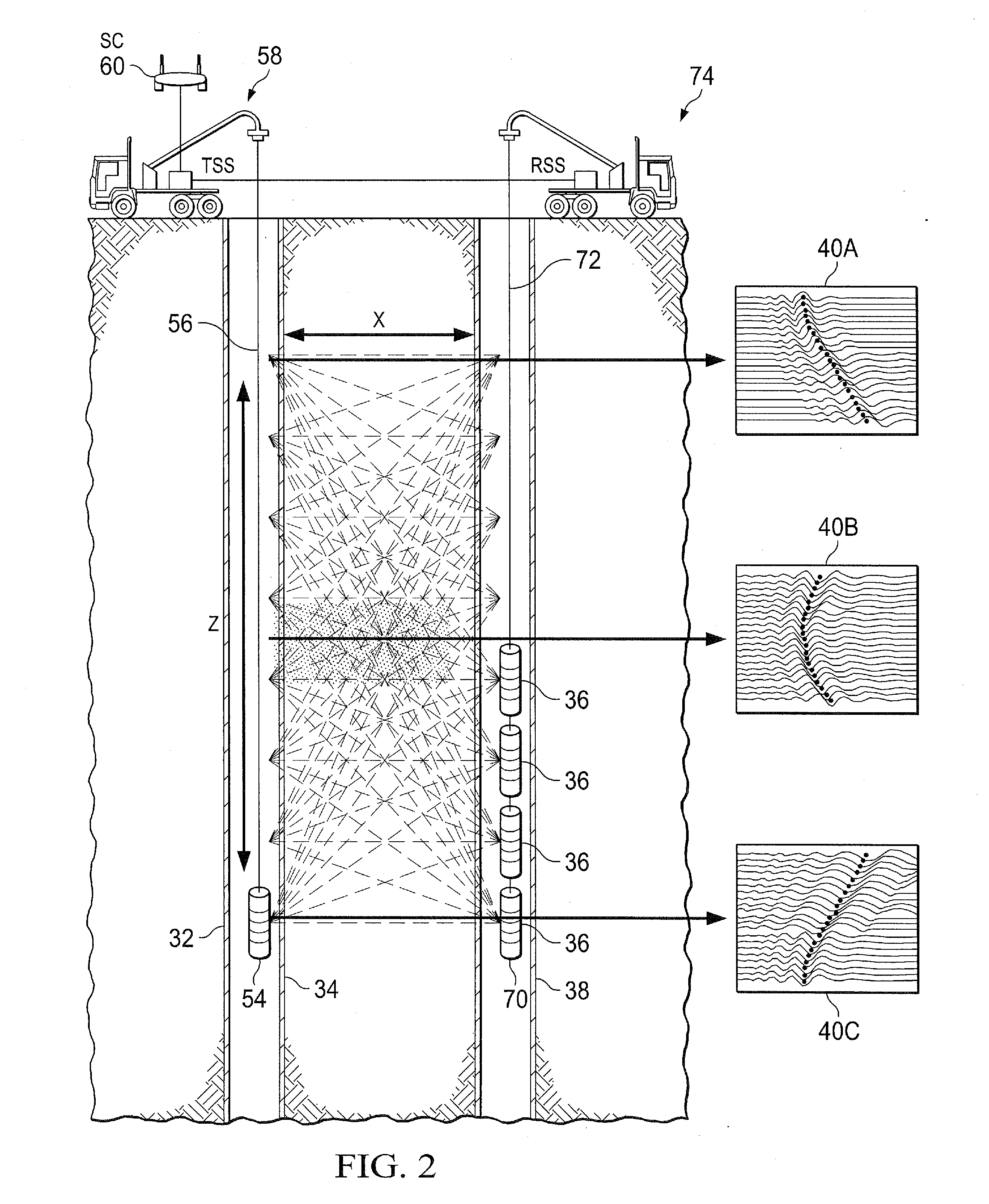
[0026]By way of introduction, the present invention involves imaging sub-surface structures, particularly hydrocarbon reservoirs and fluids therein. The primary approach is related to cross-well and borehole-to-surface electromagnetic (EM) survey technology. The present invention specifically focuses on fully time-domain data acquisition using high-power pulsed EM sources. The present invention can also include spatial over-sampling and super-resolution data processing technology to improve image resolution. The present invention can also utilize magnetic materials to provide image contrast for regions containing injected fluids.

[0027]An improved approach to cross-well EM imaging is provided, using a combination of high-power pulsed magnetic field sources, fully time-domain signal acquisition, modern low-noise magnetic field sensors, spatial oversampling and super-resolution image enhancement and injected magnetic nanofluids. The approach provided by the present invention generates ...


PUM


Abstract

Cross-well electromagnetic (EM) imaging is performed using high-power pulsed magnetic field sources, time-domain signal acquisition, low-noise magnetic field sensors, spatial oversampling and super-resolution image enhancement and injected contrast fluids. The contrast fluids increase the electromagnetic character of the formation and fluids, either the magnetic permeability or the dielectric permittivity. The acquired signals are processed and inter-well images are generated mapping electromagnetic (EM) signal speed (group velocity) rather than conductivity maps. EM velocity maps with improved resolution for both native and injected fluids are provided.

Description

CROSS REFERENCE TO RELATED APPLICATIONS[0001]The present application is a continuation in part of, and claims priority to, co-pending, commonly owned U. S. patent application Ser. No. 14 / 187,968, filed Feb. 24, 2014, and commonly-owned U.S. patent application Ser. No. 13 / 707,721, filed Dec. 7, 2012, and to its related U.S. Provisional Application No. 61 / 568,403, filed Dec. 8, 2011, priority for each of which is claimed under 35 U.S.C. §120.BACKGROND OF THE INVENTION[0002]1. Field of the Invention[0003]The present invention relates to imaging sub-surface structures, particularly hydrocarbon reservoirs and fluids therein, and more particularly to cross-well and borehole-to-surface electromagnetic (EM) surveying.[0004]2. Description of the. Related Art[0005]Cross-well and borehole-to-surface electromagnetic (EM) surveying have involved continuous-wave (CW) EM sources placed in one borehole and receivers / sensors which detected the phase and amplitude of the EM signal in a distal borehol...

Claims


Application Information

Patent Timeline
IPC IPC(8): G01V3/08
CPCG01V2003/084G01V3/083G01V3/12G01V3/30
Inventor SCHMIDT, HOWARD K.
Owner SAUDI ARABIAN OIL CO
Why Eureka
Try Eureka