
Ultrasonic measuring device, ultrasonic image device, and method for processing ultrasonic image

a technology of ultrasonic image and measuring device, which is applied in the direction of instruments, specific gravity measurement, applications, etc., can solve the problems of inability to reduce the spread of reception signal to a satisfactory level, inability to calculate and store significant amounts of data, and inability to generate ultrasonic images efficiently. , to achieve the effect of high spatial resolution

Active Publication Date: 2014-12-04
SEIKO EPSON CORP
View PDF6 Cites 1 Cited by
  • Summary
  • Abstract
  • Description
  • Claims
  • Application Information

AI Technical Summary

Benefits of technology

This patent describes an ultrasonic measuring device and method that can create high-quality ultrasonic images. The device uses an improved process to generate high-resolution images, which can help with medical diagnostics and other applications that require detailed ultrasonic imaging.

Problems solved by technology

Ultrasonic diagnostic devices have a problem in that a signal obtained by emitting ultrasound from an ultrasonic transducer and receiving the ultrasound reflected by a target subject by the ultrasonic transducer convolves narrow band characteristics of the ultrasonic transducer, and thus the reflected signal has a wide pulse width even if the target subject is a spot, resulting in an ultrasonic image in which the target subject appears stretched.
This method, however, requires a significant amount of calculation time and memory, and also has a problem in that the spreading of the reception signal cannot be reduced to a satisfactory level because phase characteristics are not included in the transfer function.

Method used


Image

  • Ultrasonic measuring device, ultrasonic image device, and method for processing ultrasonic image
  • Ultrasonic measuring device, ultrasonic image device, and method for processing ultrasonic image
  • Ultrasonic measuring device, ultrasonic image device, and method for processing ultrasonic image

Examples


Embodiment Construction

[0049]The following is a detailed description of preferred embodiments of the invention. Note that the embodiments described below are not intended to unduly limit the content of the invention recited in the claims, and all of the configurations described in the embodiments are not necessarily essential as solutions provided by the invention.

[0050]1. Basic Configuration Example of Ultrasonic Measuring Device

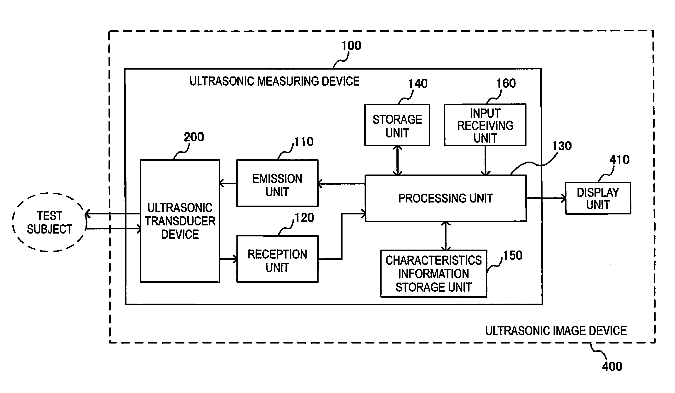
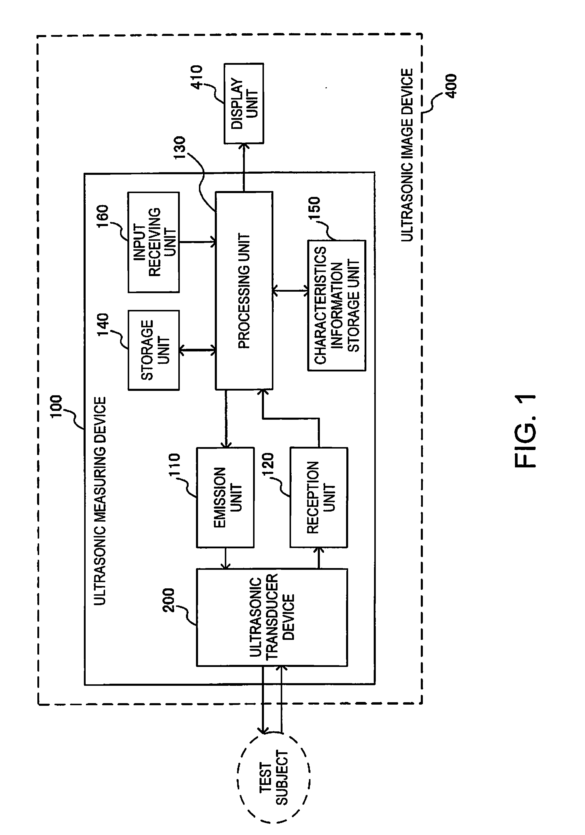
[0051]FIG. 1 shows an example of the basic configurations of an ultrasonic measuring device 100 and an ultrasonic image device 400 of this embodiment. The ultrasonic measuring device 100 of this embodiment includes an ultrasonic transducer device 200, an emission unit 110, a reception unit 120, a processing unit 130, a storage unit 140, a characteristics information storage unit 150, and an input receiving unit 160. The ultrasonic image device 400 includes the ultrasonic measuring device 100 and a display unit 410. Note that the ultrasonic measuring device 100 and the ultrasonic ...


PUM


Abstract

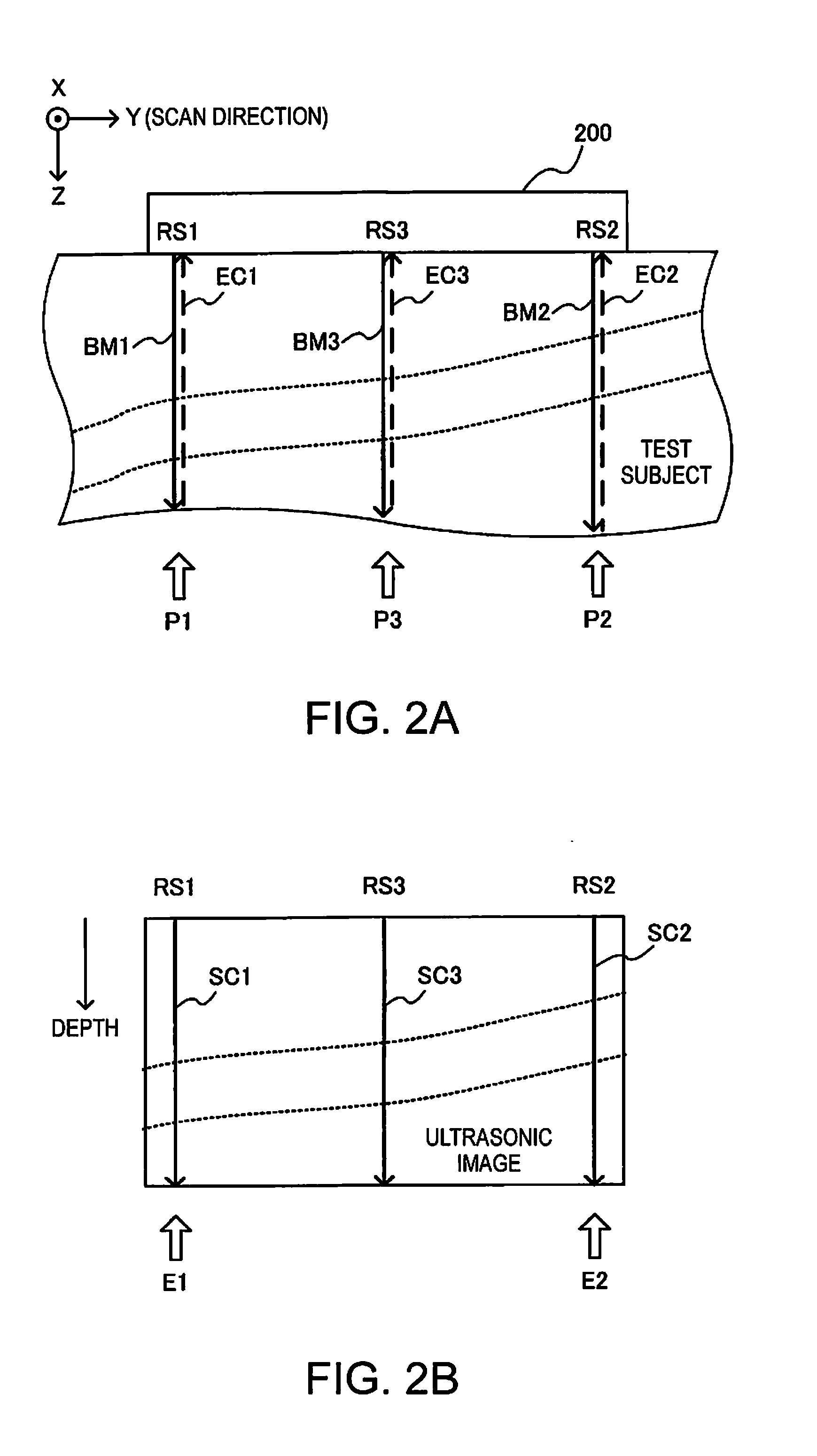
An ultrasonic measuring device including: an ultrasonic transducer device; an emission unit for emitting an ultrasonic beam; a reception unit for receiving an ultrasonic echo reflected by a test subject; and a processing unit for processing reception, wherein the processing unit identifies a transfer function with respect to the ultrasonic transducer device and the test subject based on a first reception signal corresponding to an ultrasonic beam radiated to a first area in the test subject, a second reception signal corresponding to an ultrasonic beam radiated to a second area in the test subject, and a third reception signal corresponding to an ultrasonic beam radiated to a third area located between the first area and the second area in the test subject, and performs ultrasonic image generation processing including filter processing using a deconvolution filter including the transfer function performed on the reception signals.

Description

BACKGROUND[0001]1. Technical Field[0002]The present invention relates to an ultrasonic measuring device, an ultrasonic image device, and a method for processing an ultrasonic image, and the like.[0003]2. Related Art[0004]Ultrasonic diagnostic devices have a problem in that a signal obtained by emitting ultrasound from an ultrasonic transducer and receiving the ultrasound reflected by a target subject by the ultrasonic transducer convolves narrow band characteristics of the ultrasonic transducer, and thus the reflected signal has a wide pulse width even if the target subject is a spot, resulting in an ultrasonic image in which the target subject appears stretched.[0005]To address this problem, in order to improve the resolution of ultrasonic images, a technique is known for obtaining an ultrasonic image having a high spatial resolution by removing the narrow band characteristics of the ultrasonic transducer convolved in the reception signal with the use of a filter (deconvolution fil...

Claims


Application Information

Patent Timeline
IPC IPC(8): G01N29/44
CPCG01N29/44G01N29/11A61B8/4405A61B8/4427A61B8/4483A61B8/4494G01N29/4472G01N29/46G01N29/52G01N2291/02475G01N2291/044
Inventor TSURUNO, JIROKANAI, HIROSHIHASEGAWA, HIDEYUKI
Owner SEIKO EPSON CORP
Learn More