Ion Mobility Separation Device

a technology of mobility separation and separation device, which is applied in the direction of separation process, particle separator tube details, instruments, etc., can solve the problems of large potential difference, relatively long ims device, and electric breakdown of drift gas, so as to reduce absolute voltage, reduce the risk of electrical breakdown, and reduce the absolute voltage

Active Publication Date: 2014-12-04
MICROMASS UK LTD
View PDF3 Cites 8 Cited by
  • Summary
  • Abstract
  • Description
  • Claims
  • Application Information

AI Technical Summary

Benefits of technology

[0059]The preferred embodiment helps to solve the problem of the requirement for physically long drift regions to achieve higher mobility resolution and reduces the absolute voltage required to achieve the resolution, thus minimising the use of hazardous voltages and the risk of electrical breakdown.

Problems solved by technology

However, this will ultimately result in electrical breakdown in the drift gas.
However, this leads to a relatively long IMS device and the use of a larger potential difference in order to maintain the same electric field strength over the longer drift region.
This necessitates the use of high absolute voltages, which may result in hazardous electrical discharges to the surrounding areas.

Method used


Image

  • Ion Mobility Separation Device
  • Ion Mobility Separation Device
  • Ion Mobility Separation Device

Examples


Embodiment Construction

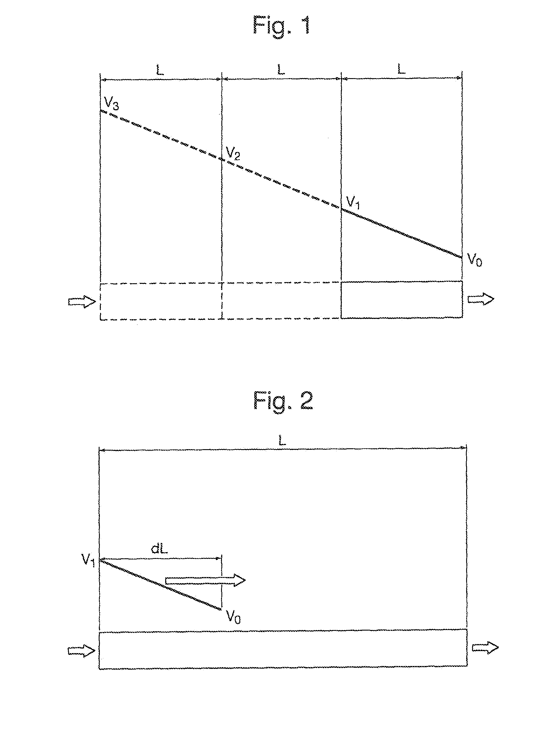
[0070]The resolving power R of an ion mobility spectrometer (IMS) that uses a uniform electric field is given by the expression:

R=ttFWHM=(LEze16kTln2)0.5=(Vze16kTln2)0.5

wherein t is the ion drift time through the drift region of the device; tFWHM is the peak width at half height of the signal; L is the length of the drift region; E the electric field strength; z is the charge on the ion being analysed; e is the unit electronic charge; V is the potential difference across the drift region of the device (E=V / L); k is Boltzmann's constant; and T is the temperature of the drift gas in the drift region.

[0071]It is apparent from the above expression that the potential difference V across the drift region of the IMS device can be increased in order to increase the resolution of the device. However, increasing the potential difference across a fixed length of drift region will ultimately result in electrical breakdown in the drift gas. In order to further increase the resolution of the devi...


PUM


Abstract

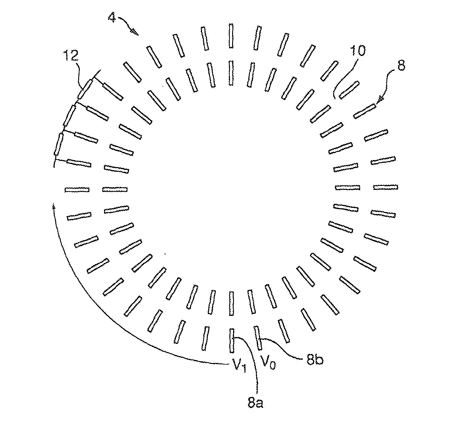
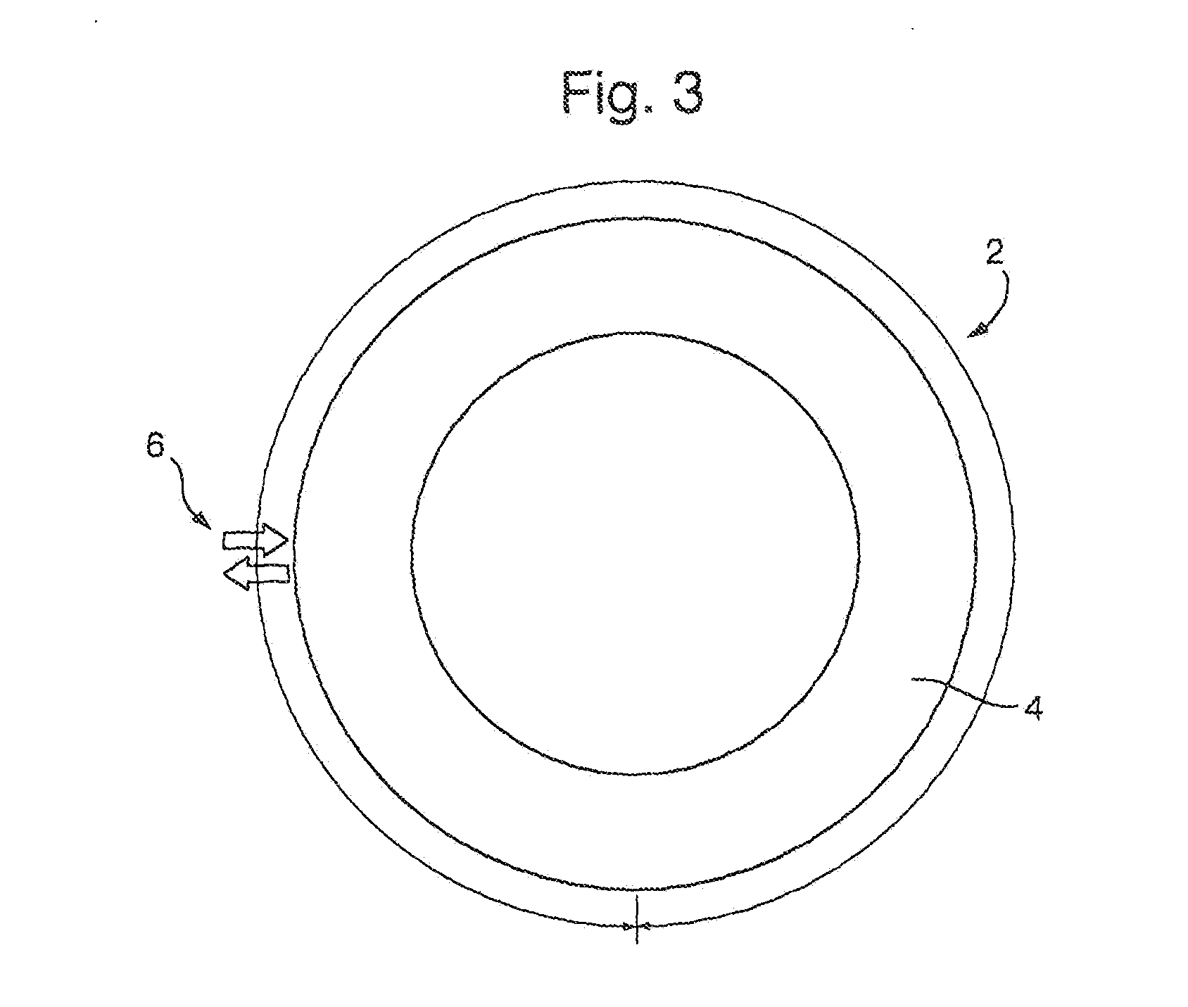
An ion mobility separator 4 and a method of separating ions according to their ion mobility are disclosed. An RF ion guide is provided having a plurality of electrodes that are arranged to form an ion guiding path that extends in a closed loop. RF voltages are supplied to at least some of the electrodes in order to confine ions within said ion guiding path. A DC voltage gradient is maintained along at least a portion of a longitudinal axis of the ion guide, wherein the voltage gradient urges ions to undergo one or more cycles around the ion guide and thus causes the ions to separate according to their ion mobility as the ions pass along the ion guide. The closed loop ion guide enables the resolution of the ion mobility separator to be increased without necessitating a large device, since the drift length through the device can be increased by causing the ions to undergo multiple cycles around the device.

Description

CROSS-REFERENCE TO RELATED APPLICATION[0001]None.BACKGROUND TO THE PRESENT INVENTION[0002]It is known to apply a uniform electric field across a drift region of an ion mobility spectrometer (IMS) in order to separate ions according to their ion mobilities. It is desirable to provide such devices with relatively high resolution. It is possible to increase the resolution of such a device by increasing the electric field strength in the drift region. However, this will ultimately result in electrical breakdown in the drift gas. In order to increase the resolution of the device it is therefore conventionally considered necessary to increase the length of the drift region, whilst maintaining the electric field strength. However, this leads to a relatively long IMS device and the use of a larger potential difference in order to maintain the same electric field strength over the longer drift region. This necessitates the use of high absolute voltages, which may result in hazardous electric...

Claims


Application Information

Patent Timeline
Patent Type & Authority Applications(United States)
IPC IPC(8): H01J49/00H01J49/06H01J49/36
CPCH01J49/0031H01J49/062H01J49/36H01J49/065G01N27/623H01J49/26H01J49/4235
Inventor GILES, KEVINWILDGOOSE, JASON LEE
Owner MICROMASS UK LTD
Why Eureka
Try Eureka