
Surface patch techniques for computational geometry

a surface patch and computational geometry technology, applied in the field of computer-aided design systems and methods, can solve the problems of inability to easily and efficiently interpolate from other subportions, no cad system wherein a designer (or more generally, a user) of geometric objects can easily and efficiently, and designers/users may encounter long delays. , to achieve the effect of improving visual and functional characteristics, and increasing the exactness of surface conversions

Inactive Publication Date: 2014-12-04
CAD-SENSE LLC
View PDF0 Cites 12 Cited by
  • Summary
  • Abstract
  • Description
  • Claims
  • Application Information

AI Technical Summary

Benefits of technology

The system allows for efficient and intuitive design of geometric objects with improved surface smoothness and precision, reducing computational overhead and enabling real-time modifications, while facilitating the conversion of high-degree surfaces to lower-degree surfaces for better compatibility with commercial modelers.

Problems solved by technology

Thus, the designer typically constructs such feature curves and positions them where the intended surface is likely to change its geometric shape in a way that cannot be easily interpolated from other subportions of the surface already designed.
There has heretofore, however, been no CAD system wherein a designer (or more generally, user) of geometric objects can easily and efficiently express his / her design intent by inputting constraints and having the resulting geometric object be fair.
That is, the designer / user may encounter lengthy delays due to substantial computational overhead and / or the designer / user may be confronted with non-intuitive geometric object definition and deformation techniques that require substantial experience to effectively use.
For example, many prior art CAD systems provide techniques for allowing surfaces to be designed and / or deformed by defining and / or manipulating designated points denoted as “control points.” However, such techniques can be computationally expensive, non-intuitive, and incapable of easily deforming more than a local area of the surface associated with such a control point.
However, a designer's intent may not easily correspond to a surface design technique using such control vectors since each of the control vectors typically corresponds to only a single point of the surface isolated from other surface points having corresponding control vectors.
Thus, such techniques are, at most, only able to deform an area of the surface local to such points having corresponding control vectors.
Additionally, such prior art CAD systems may also have difficulties in precisely performing blending and trimming operations.
For example, two geometric objects intended to abut one another along a common boundary may not be within a insufficient tolerance to one another at the boundary.
That is, there may be sufficiently large gaps between the geometric objects that the boundary may not be considered “water tight,” which may be problematic in certain machining operations and other operations like Boolean operations on solids.
However, such flexibility comes at a price; e.g., geometric objects generated from high degree polynomial mappings are computationally expensive to generate and manipulate.
Additionally, such high degree polynomial mappings can also affect the precision of various computations, e.g., due to the accumulation of computational errors.
In particular, if the polynomial degree of the geometric object is imported directly into such a modeler, and the object's degree is above such the maximum recommended degree for the modeler, unexpected results may occur, e.g., the modeler may crash, an unacceptable build up computational errors may occur, and / or very lengthy processing times may be experienced, or even worse, undetected errors / inaccuracies may be incorporated into a geometric model generated by the modeler.
However, such a conversion presents its own set of difficulties.
In particular, there may be both computational efficiency difficulties and possibly difficulties maintaining certain tolerances in the target modeler.
Moreover, there is very likely to be inaccuracies in the conversion process.
However, it is nontrivial to quantitatively measure what is meant by “smoothness”.
However, this measure of smoothness does not always work for parametric functions used in design.
This poses a problem for parametric forms that is not seen in explicit forms where the derivative is a scalar—the slope.
This type of evaluation is usually fast and efficient, but does not give function values at chosen positions between the increments.

Method used


Image

  • Surface patch techniques for computational geometry
  • Surface patch techniques for computational geometry
  • Surface patch techniques for computational geometry

Examples


Embodiment Construction

1. Introduction

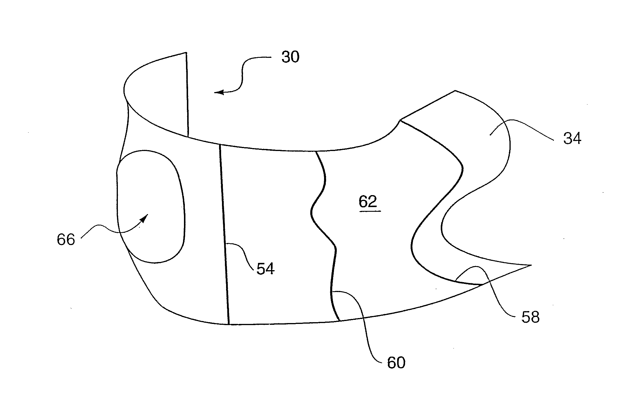
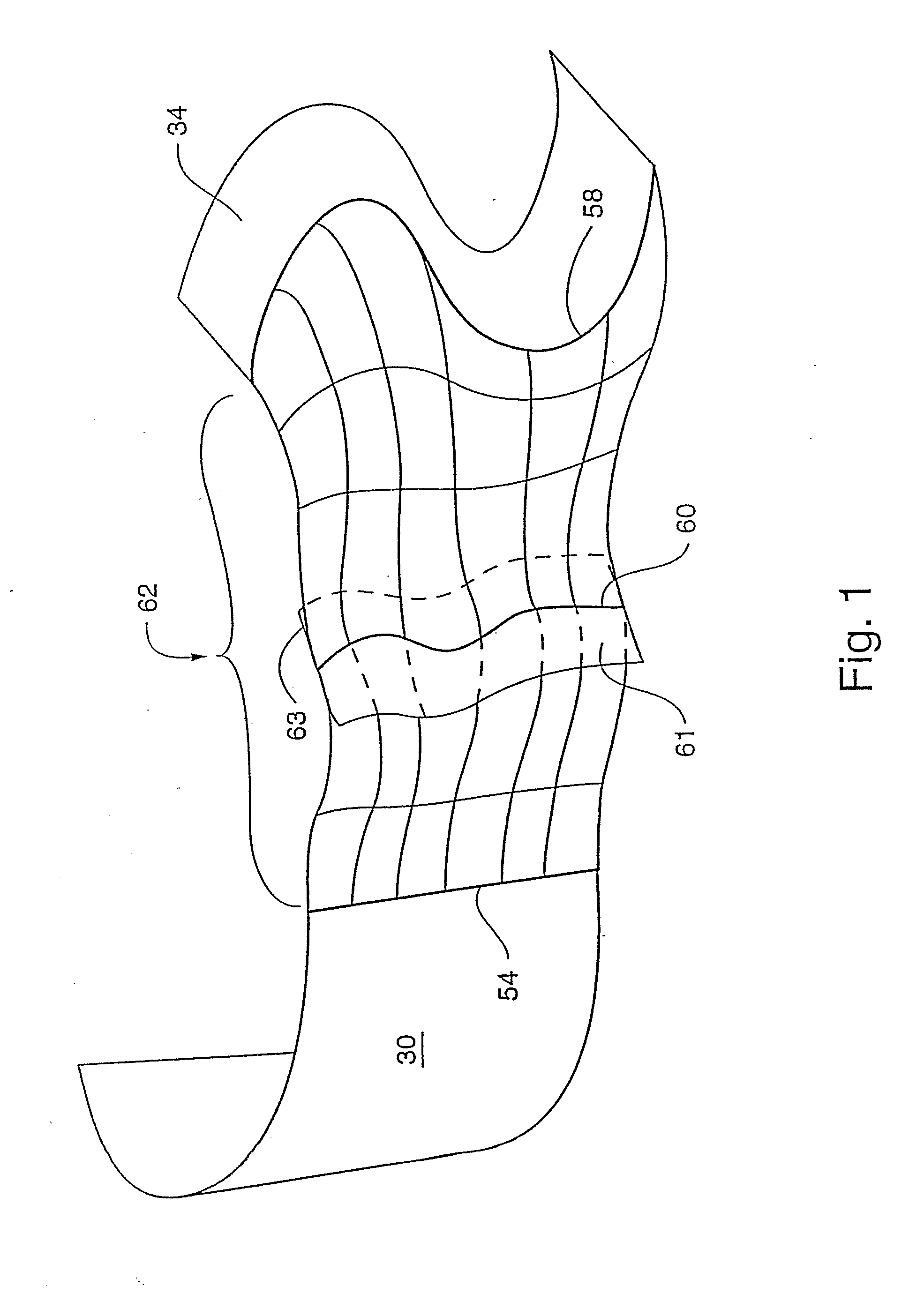
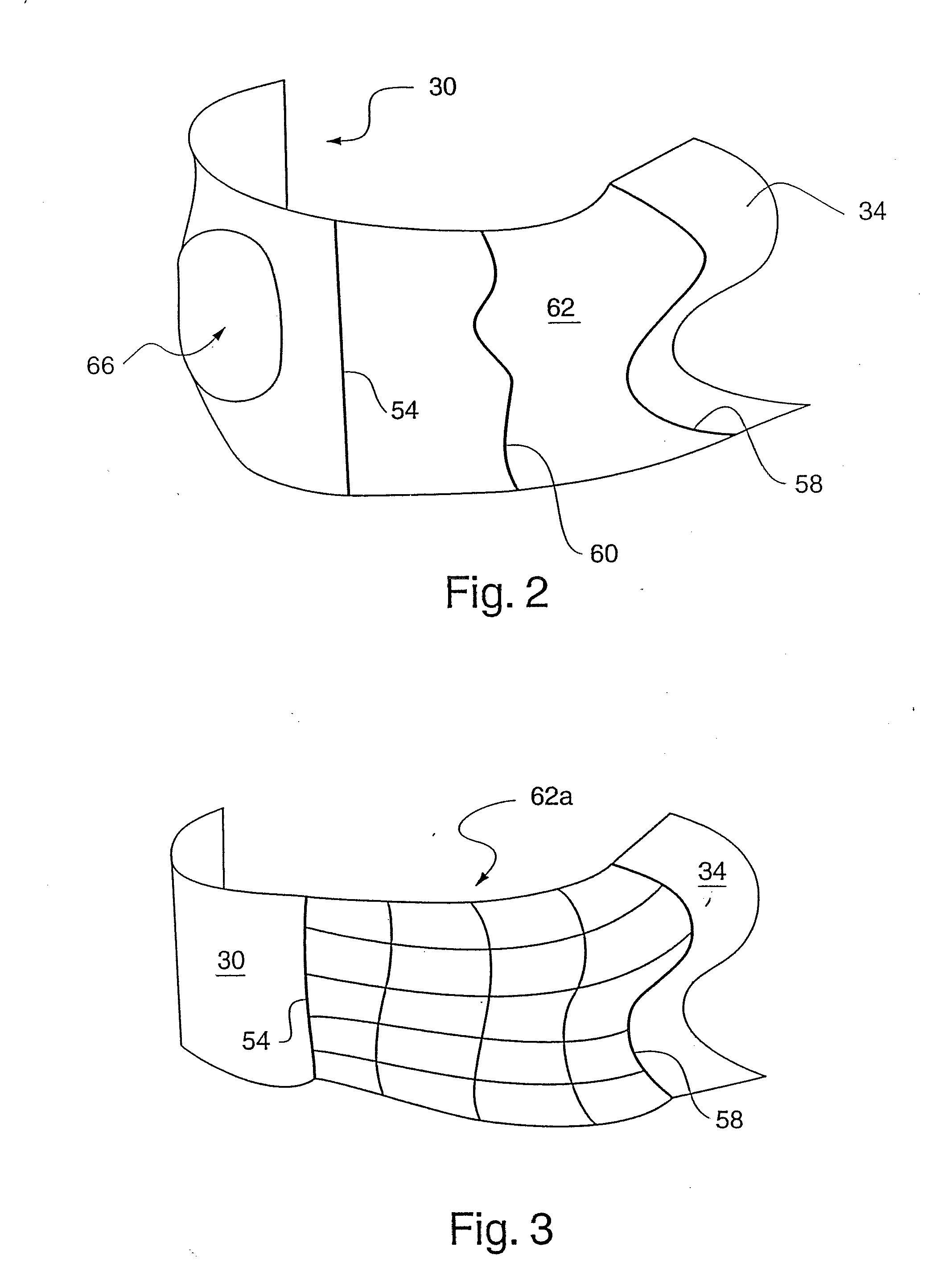
[0133]FIG. 1 illustrates the use of an embodiment of the present disclosure for designing a surface 62 that interpolates any two parametric surfaces such as between the half cylinder surface 30 and the surface 34. That is, the surface 62 is generated via a novel surface interpolation process, wherein constraints on surface 62 shape are provided by the feature curves 54, 58 and 60, and their associated novel control geometry (e.g., isocline ribbons). In particular, the following constraints are satisfied by the surface 62:[0134](a) one or more geometric characteristics of the surface 30 along the feature curve 54 are imposed on the surface 62,[0135](b) one or more geometric characteristics of the surface 34 along the feature curve 58 are imposed on the surface 62, and[0136](c) the surface 62 interpolates through the feature curve 60, wherein the surface 62 tangents along the extent of curve 60 are derived from (e.g., identical to) the isocline ribbons 61 and 63.

[0137]T...


PUM


Abstract

A method and system for computer aided design (CAD) is disclosed for designing geometric objects, wherein interpolation and / or blending between such objects is performed while deformation data is being input. Thus, a designer obtains immediate feedback to input modifications without separately entering a command(s) for performing such deformations. A novel N-sided surface generation technique is also disclosed herein to efficiently and accurately convert surfaces of high polynomial degree into a collection of lower degree surfaces. E.g., the N-sided surface generation technique disclosed herein subdivides parameter space objects (e.g., polygons) of seven or more sides into a collection of subpolygons, wherein each subpolygon has a reduced number of sides. More particularly, each subpolygon has 3 or 4 sides. The present disclosure is particularly useful for designing the shape of surfaces. Thus, the present disclosure is applicable to various design domains such as the design of, e.g., bottles, vehicles, and watercraft. Additionally, the present disclosure provides for efficient animation via repeatedly modifying surfaces of an animated object such as a representation of a face.

Description

CROSS REFERENCE TO RELATED APPLICATIONS[0001]The present application claims the benefit of U.S. Provisional Patent Application Ser. No. 61 / 135,341 filed Jul. 18, 2008, and claims the benefit of U.S. Provisional Patent Application Ser. No. 61 / 211,714 filed Apr. 1, 2009; the present application is also a continuation-in-part of U.S. patent application Ser. No. 11 / 733,122 filed Apr. 9, 2007, which is a division of U.S. patent application Ser. No. 10 / 689,693 filed Oct. 20, 2003 (now U.S. Pat. No. 7,236,167), which is a division of U.S. patent application Ser. No. 09 / 360,029 filed Jul. 23, 1999 (now U.S. Pat. No. 7,196,702), which claims the benefit of the following two provisional applications: U.S. Provisional Application Ser. No. 60 / 093,892, filed Jul. 23, 1998, and U.S. Provisional Application Ser. No. 60 / 116,199, filed Jan. 15, 1999, all of the above-referenced applications are incorporated herein by reference in their entirety.FIELD OF THE INVENTION[0002]The present invention relat...

Claims


Application Information

Patent Timeline
Patent Type & Authority Applications(United States)
IPC IPC(8): G06T15/10
CPCG06T15/10G06T17/10G06T17/30G06F30/10G06F2111/04G06F30/00G06F17/10
Inventor ROCKWOOD, ALYN P.
Owner CAD-SENSE LLC
Learn More