Devices And Methods For Cooling Components On A PCB

a technology of cooling components and cooling components, applied in the direction of electrical equipment, electrical apparatus, printed circuit aspects, etc., can solve the problems of increasing the likelihood of a fault developing, increasing the risk of components being damaged, and adding unnecessary costs, so as to achieve more efficient cooling of components

Active Publication Date: 2014-12-04
NIDEC CONTROL TECHN LTD
View PDF10 Cites 11 Cited by
  • Summary
  • Abstract
  • Description
  • Claims
  • Application Information

AI Technical Summary

Benefits of technology

[0014]In one particular aspect of the invention, a duct or conduit may be formed of a plurality of structural boards such that the conduit has an n-sided polygonal cross-section. If n=3, at least one of the boards may be a PCB; if n=4 and if the cross-section of the conduit is rectangular, at least two or three of the boards may be PCBs; and if n>4, at least one of the boards may be a PCB. At least one of the PCBs may comprise apertures formed therein for allowing air to be forced therethrough, either into or out of the duct. Such airflow may cool downstream portions of components on the one or more PCBs.
[0015]In a second aspect of the invention, there is provided a...

Problems solved by technology

When many such components are installed on a PCB, the heat generated can be relatively concentrated and, if not managed efficiently, risks damage to the components through over-heating, short circuits, etc.
Whilst multiple fans or air directors may be used to blow air ...

Method used


Image

  • Devices And Methods For Cooling Components On A PCB
  • Devices And Methods For Cooling Components On A PCB
  • Devices And Methods For Cooling Components On A PCB

Examples


Embodiment Construction

[0040]The present invention seeks to provide improved devices and methods for cooling electronic components on a PCB. Whilst various embodiments of the invention are described below, the invention is not limited to these embodiments, and variations of these embodiments may well fall within the scope of the invention which is to be limited only by the appended claims.

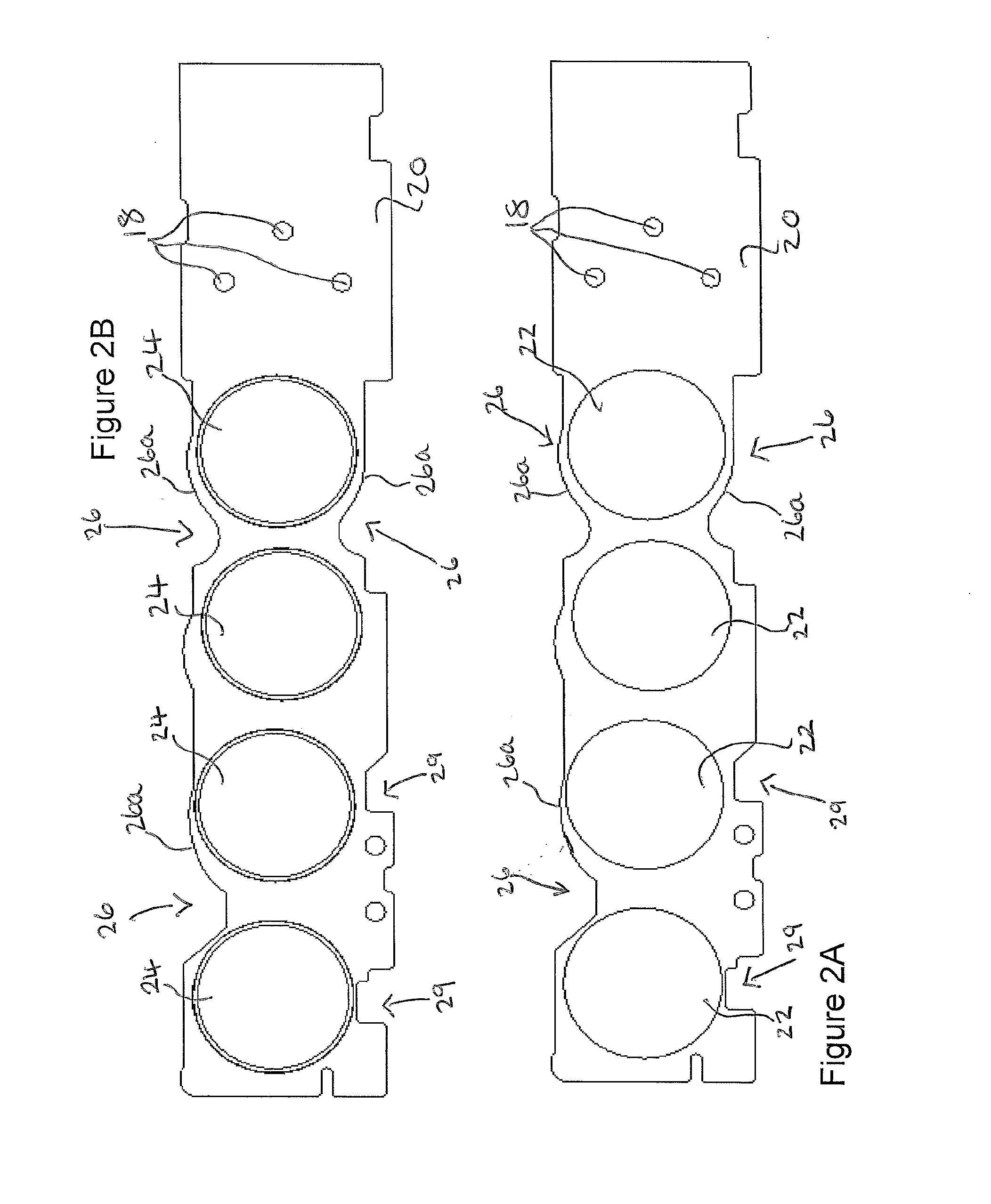
[0041]In accordance with a first embodiment of the present invention, there is shown in FIGS. 2A and 2B a contoured PCB 20. In particular, FIG. 2A shows PCB 20 from above prior to having components installed or otherwise received thereon, whilst FIG. 2B shows PCB 20 with capacitors 24 received thereon. In FIG. 2A, PCB 20 comprises four circular component areas 22, each arranged to receive one of capacitors 24. Other shapes of component areas may be used, and their position on PCB 20 may vary from one embodiment to the other. For example, component areas 22 may be rectangular-shaped. Component areas 22 may be virtual area...


PUM


Abstract

There is described an electronic assembly comprising a structure and a printed circuit board (PCB) connected to the structure to form a duct. The PCB has a first side arranged to receive one or more heat-generating components, and a second side. The PCB comprises one or more apertures formed therein. The electronic assembly further comprises airflow generating means arranged to generate an airflow along the duct and along the second side of the PCB such that air is forced through the one or more apertures. By forming a duct beneath a PCB and allowing air to be forced through apertures formed in the PCB, more efficient cooling of components on the PCB may be achieved. For example, the position of the apertures may be tailored such that specific components, or specific parts of components, may be exposed to airflow through the apertures.

Description

CROSS-REFERENCE TO RELATED APPLICATIONS[0001]This application claims the benefit and priority of Indian Patent Application No. 1205 / MUM / 2013 filed Mar. 28, 2013 and Great Britain Patent Application No. 1309776.1 filed May 31, 2013. The entire disclosures of the above applications are incorporated herein by reference.FIELD OF THE INVENTION[0002]The present invention relates to devices and methods for cooling components on a printed circuit board (PCB). In particular, the invention relates to an electronic assembly for cooling one or more heat-generating components on a PCB, as well as to a method of cooling the components using the assembly. The invention furthermore relates to a PCB that may be used with the assembly for the cooling of components on the PCB.BACKGROUND TO THE INVENTION[0003]Electronic components generate heat as current passes through them. When many such components are installed on a PCB, the heat generated can be relatively concentrated and, if not managed efficien...

Claims


Application Information

Patent Timeline
IPC IPC(8): H05K7/20H05K1/02
CPCH05K1/0201H05K7/20145H05K7/20909H05K1/0209H05K1/0272H05K2201/09063H05K2201/09145H05K2203/081
Inventor PATIL, SHASHIKANT DHONDOPANTKURKURE, VINAYAK LATAHOLMAN-WHITE, JONATHAN ROBERT
Owner NIDEC CONTROL TECHN LTD
Why Eureka
Try Eureka