Control device for use with switching converters

a control device and converter technology, applied in the direction of electric variable regulation, process and machine control, instruments, etc., can solve the problems of affecting the reliability, lifetime and luminous decay of leds, affecting the stability of the circuit, and weakening the electrical isolation, so as to achieve stable system, high pfc, and constant output current

Active Publication Date: 2014-12-04
SI EN TECH XIAMEN
View PDF4 Cites 31 Cited by
  • Summary
  • Abstract
  • Description
  • Claims
  • Application Information

AI Technical Summary

Benefits of technology

[0021]Compared with conventional technologies, the control device for use with the switching converting module has the following advantages: 1) a high PFC and constant output current can be obtained without any optical coupler and loop compensation, and the system is stable; 2) the one-s

Problems solved by technology

As a result, a constant voltage source driver may not ensure the brightness of the LED to be uniform, and may affect the reliability, lifetime and luminous decay of the LED as well.
However, the optical coupler has aging issue, which may affect the stability of the circuit and weaken the electrical isolation.
On the other hand, the wide use of power electronics could cause serious pollution to the utility power grid, and therefore the reactive power draws more and more

Method used


Image

  • Control device for use with switching converters
  • Control device for use with switching converters
  • Control device for use with switching converters

Examples


Embodiment Construction

[0029]The following detailed description refers to the accompanying drawings as a part of the present application. The illustrative embodiments described in the detailed description, the accompanying drawings and the claims are not limiting, and other embodiments may be adopted, or modifications may be made without deviating from the spirit and subject of the present application. It should be understood that, the various aspects of the application described and graphically presented herein may be arranged, replaced, combined, divided and designed in many different configurations, and these different configurations are implicitly included in the application.

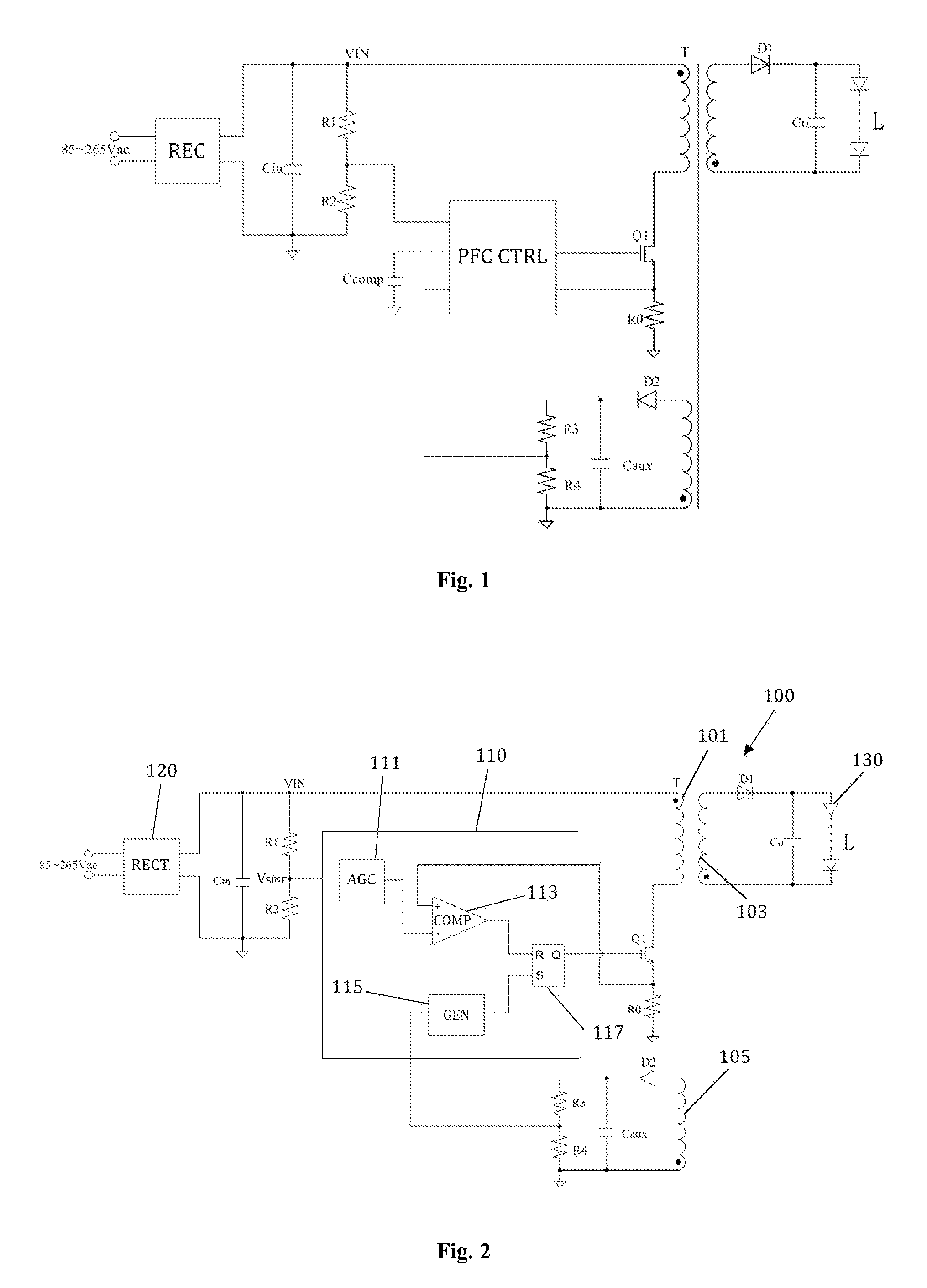
[0030]FIG. 2 shows a diagram of a control device 110 for use with a fly-back converter 100 according to an embodiment of the present application. The fly-back converter 100 is a converting module that receives an input power at its primary winding and outputs an output power at its secondary winding.

[0031]The control device 110 is...


PUM


Abstract

The present application provides a control device for controlling a switching converting module to generate an output signal of constant output current from a rectified AC power supply signal. The switching converting module comprises a primary winding for receiving the rectified AC power supply signal and a power switch coupled in series with the primary winding. The control device comprises: an AGC amplifier configured to receive a first sampling signal sampled from the rectified AC power supply signal, and to generate a reference signal of constant amplitude according to the first sampling signal; a signal comparator configured to compare the reference signal with a current sensing signal in proportion to a primary side current flowing through the primary side winding to generate a comparison signal; a signal generator configured to receive a second sampling signal sampled from the output signal, and to generate a clock signal according to the second sampling signal; and a control logic configured to generate a control signal for switching the power switch according to the comparison signal and the clock signal.

Description

FIELD OF THE INVENTION[0001]The present application relates to the switching power supply technology, particularly to a control device for a switching converter, which is suitable for use with a fly-back converter, non-isolating buck-boost converter.BACKGROUND OF THE INVENTION[0002]The light characteristics of Light Emitting Devices (LEDs) is generally characterized by a function of current rather than a function of voltage because a minor change in the forward voltage of the LED may cause a bigger change in the LED current. As a result, a constant voltage source driver may not ensure the brightness of the LED to be uniform, and may affect the reliability, lifetime and luminous decay of the LED as well. Therefore, the LEDs are generally driven by a constant current source.[0003]In consideration of safety issue, many LED luminaires require the LED driver to have the isolation function, i.e. the electrical isolation between the output of the LED luminaries and the input by the power g...

Claims


Application Information

Patent Timeline
IPC IPC(8): H02M3/335H02M1/42H05B44/00
CPCH02M3/33523H02M1/4258Y02B20/30Y02B70/10H05B45/3725H05B45/385H02M3/335H02M3/33507H02M1/0022
Inventor WU, CHAOZHENG, PENGFENG
Owner SI EN TECH XIAMEN
Why Eureka
Try Eureka