Directional coupling-type multi-drop bus

a coupling type and multi-drop technology, applied in the direction of instruments, baseband system details, optical elements, etc., can solve the problems of signal distortion, signal signal transmission speed cannot be increased, etc., to achieve the effect of increasing signal transmission speed, increasing speed, and maintaining the performance of the coupler approximately constan

Active Publication Date: 2014-12-04
KEIO UNIV
View PDF0 Cites 13 Cited by
  • Summary
  • Abstract
  • Description
  • Claims
  • Application Information

AI Technical Summary

Benefits of technology

[0051]The disclosed directional coupling-type multi-drop bus makes it possible to match the impedance of the bus at the time of coupling, and as a result, the speed of signal transfer can be increased. Moreover, a structure where the signal power is equally divided into the child boards or a structure where the performance of the co

Problems solved by technology

A multi-drop bus, however, has such a disadvantage that the transfer speed cannot be increased because the characteristic impedance discontinues at the branch points of a transmission line.
When the characteristic impedance discontinues, part of the signal is reflected, which causes distortion of the signal that has passed through.
In addition, the input capacitance of the module attached to a small transmission line (stub) at the end of a branch lowers the impedance of the branch point, which causes signal distortion, and thus, further delays the signal propagation along the bus.
When a connector is inserted into a stub so that a module can be exchanged or added, a com

Method used


Image

  • Directional coupling-type multi-drop bus
  • Directional coupling-type multi-drop bus
  • Directional coupling-type multi-drop bus

Examples


example 1

[0089]Based on the above, next, the directional coupling-type multi-drop bus according to Example 1 of the present invention is described in reference to FIGS. 2 to 15B. Here, the degree of coupling is adjusted by the thickness of the insulating film, and at the same time, the distance between coupler lines Sc>the distance to the plane h and the constant coupler line width Wc>positional error δ are satisfied.

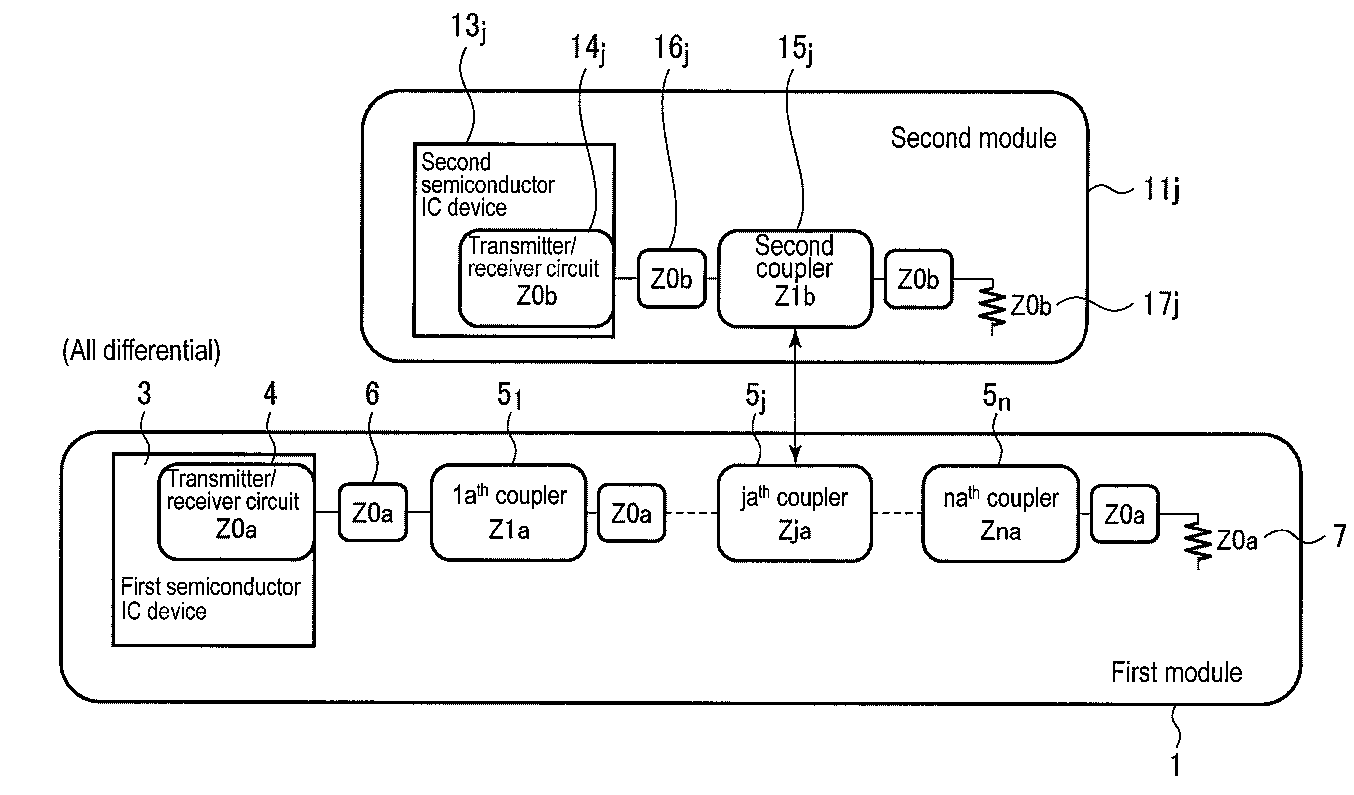
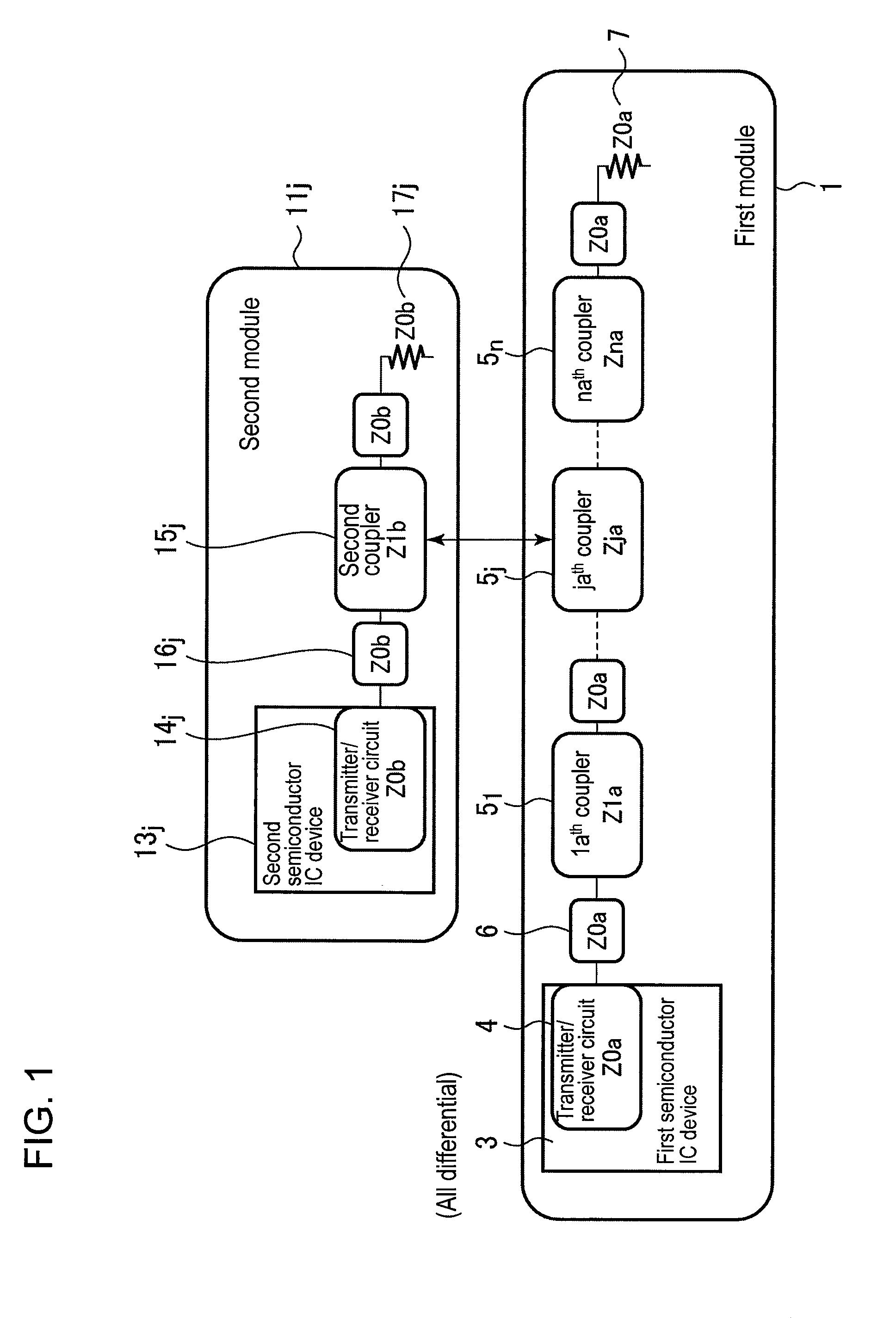
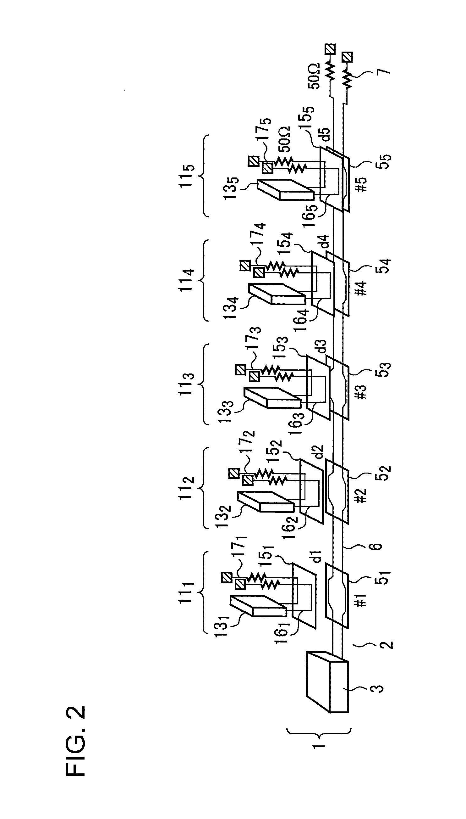
[0090]FIG. 2 is a schematic perspective diagram showing the directional coupling-type multi-drop bus according to Example 1 of the present invention. FIG. 3A is a schematic perspective diagram showing a child board, and FIG. 3B is a schematic perspective diagram showing a coupling portion. As shown in FIG. 2, bus lines (connection lines 6) are formed on a main board 2 of a number of pairs (only one pair is shown in the figure) of differential lines with a differential impedance Z (typically, 100Ω) that are wired parallel to each other from a first semiconductor integrated circui...

example 2

[0140]Next, the directional coupling-type multi-drop bus according to Example 2 of the present invention is described in reference to FIG. 17. The impedance is adjusted by varying the line width in a coupler portion in Example 2. FIG. 17 is a plan diagram showing the directional coupling-type multi-drop bus according to Example 2 of the present invention, where the greater the degree of coupling is, that is to say, the farther away the coupler is from the transmitter / receiver chip, the smaller the line width Wc of the coupler end on the main board side is, and the remaining portions are the same as in Example 1. Here, the child board in each coupler portion is the same as in Example 1. That is to say, any memory module may be mounted in any location on the main board.

[0141]In this case, the line width Wc of the coupler on the main board side is set as follows:

Wc1≧Wc2≧Wc3≧Wc4≧Wc5, where Mc1>Wc5.

When the line width Wc of a coupler is smaller, the impedance is greater as shown in FIG. ...

example 3

[0147]Next, the directional coupling-type multi-drop bus according to Example 3 of the present invention is described in reference to FIG. 19. In Example 3, the portions where a module is not mounted are not provided with a memory or a transmitter / receiver circuit, and a child board for a terminal having only a coupler and a terminal resistor is mounted. FIG. 19 is a cross-sectional diagram showing the directional coupling-type multi-drop bus according to Example 3 of the present invention, and a board for a terminal, that is to say, a terminal module 40, is mounted on a location where a memory module is not mounted. The remaining structure is the same as in Example 1. Though memory modules are mounted on both sides in this figure, memory modules may be mounted starting from an end in the order in which the degree of coupling of the directional coupler is greater as shown in FIG. 20.

[0148]This terminal module 40 is provided with a child board 41 that is the same as for the memory mo...


PUM


Abstract

The invention relates to a directional coupling-type multi-drop bus of which the impedance is matched with the bus at the time of coupling so that the speed is increased. A directional coupler is formed when a second module provided with a second coupler end is mounted on a first module provided with a first coupler end, and as a result, the coupling impedance where the proximity effects in the coupling state of the directional coupler are reflected is matched with the impedance of the bus.

Description

CROSS-REFERENCE TO RELATED APPLICATIONS[0001]This application is a continuation of International Application No. PCT / JP2013 / 053012, filed on Feb. 8, 2013, now pending, herein incorporated by reference. Further, this application is based upon and claims the benefit of priority from the prior Japanese Patent Application No. 2012-032711, filed on Feb. 17, 2012, entire contents of which are incorporated herein by reference.TECHNICAL FIELD[0002]The present invention relates to a directional coupling-type multi-drop bus, for example, a technology for signal transmission between modules such as processors and memories formed of CMOS integrated circuits, and in particular, to a multi-drop bus with increased speed where a number of modules are connected to the same transmission line for data transfer.BACKGROUND ART[0003]A multi-drop bus is a connection technology for mutual communication between a number of modules which share one transmission line (bus). In many cases, a processor and a mem...

Claims


Application Information

Patent Timeline
IPC IPC(8): G02B6/293
CPCG02B6/2932H04L25/0266H04L25/0272H04L25/0278
Inventor KURODA, TADAHIROISHIKURO, HIROKI
Owner KEIO UNIV
Why Eureka
Try Eureka