
Ridge Vent Cap

a vent cap and ridge technology, applied in ventilation systems, lighting and heating apparatus, heating types, etc., can solve the problems of end caps fashioned and bent to enclose, and cannot adequately enclose or seal the end opening of the same ridge vent on a roof having a different pitch, so as to prevent the deterioration of attic insulation and reduce cooling costs

Inactive Publication Date: 2014-12-04
STOUFFER TECH
View PDF5 Cites 8 Cited by
  • Summary
  • Abstract
  • Description
  • Claims
  • Application Information

AI Technical Summary

Benefits of technology

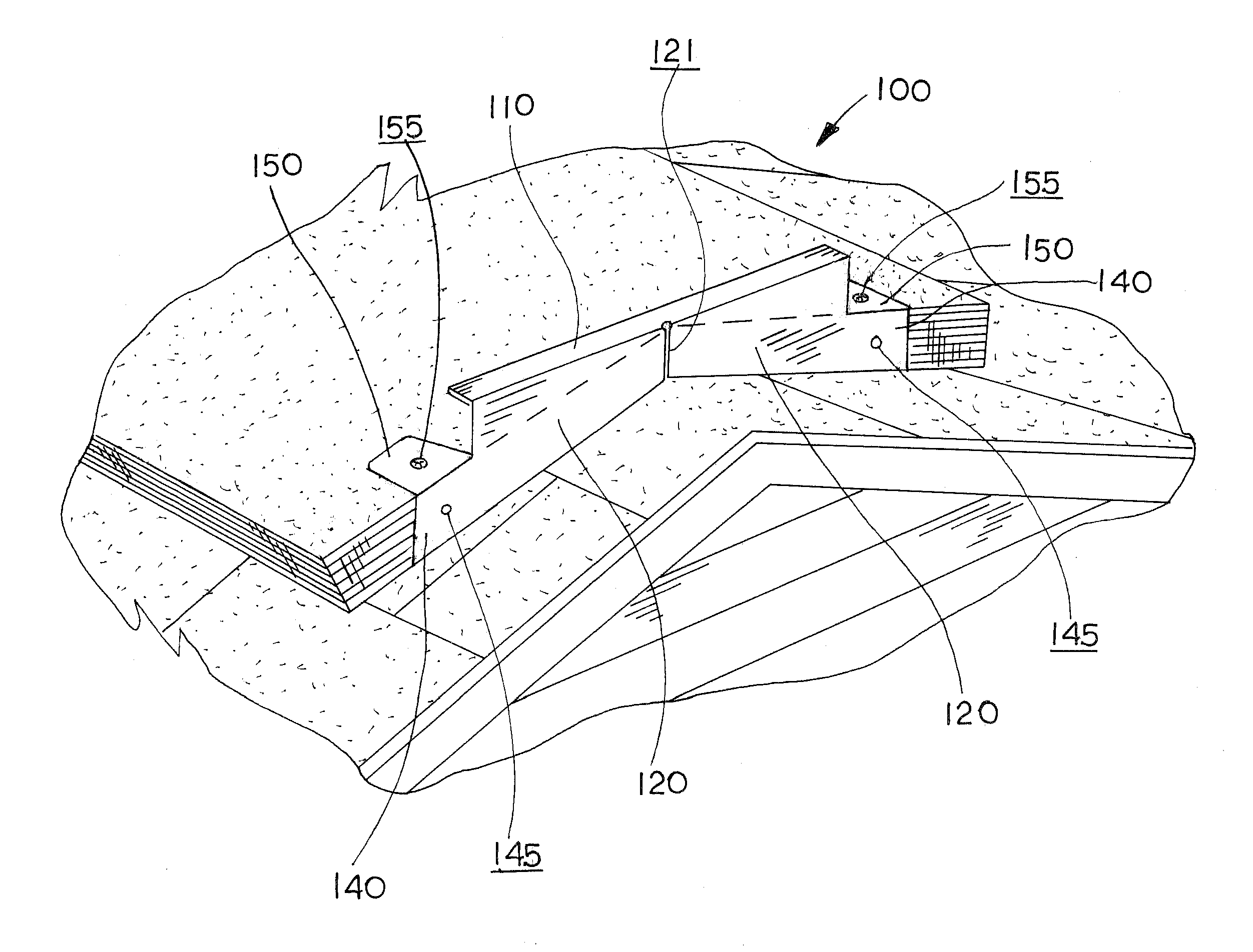
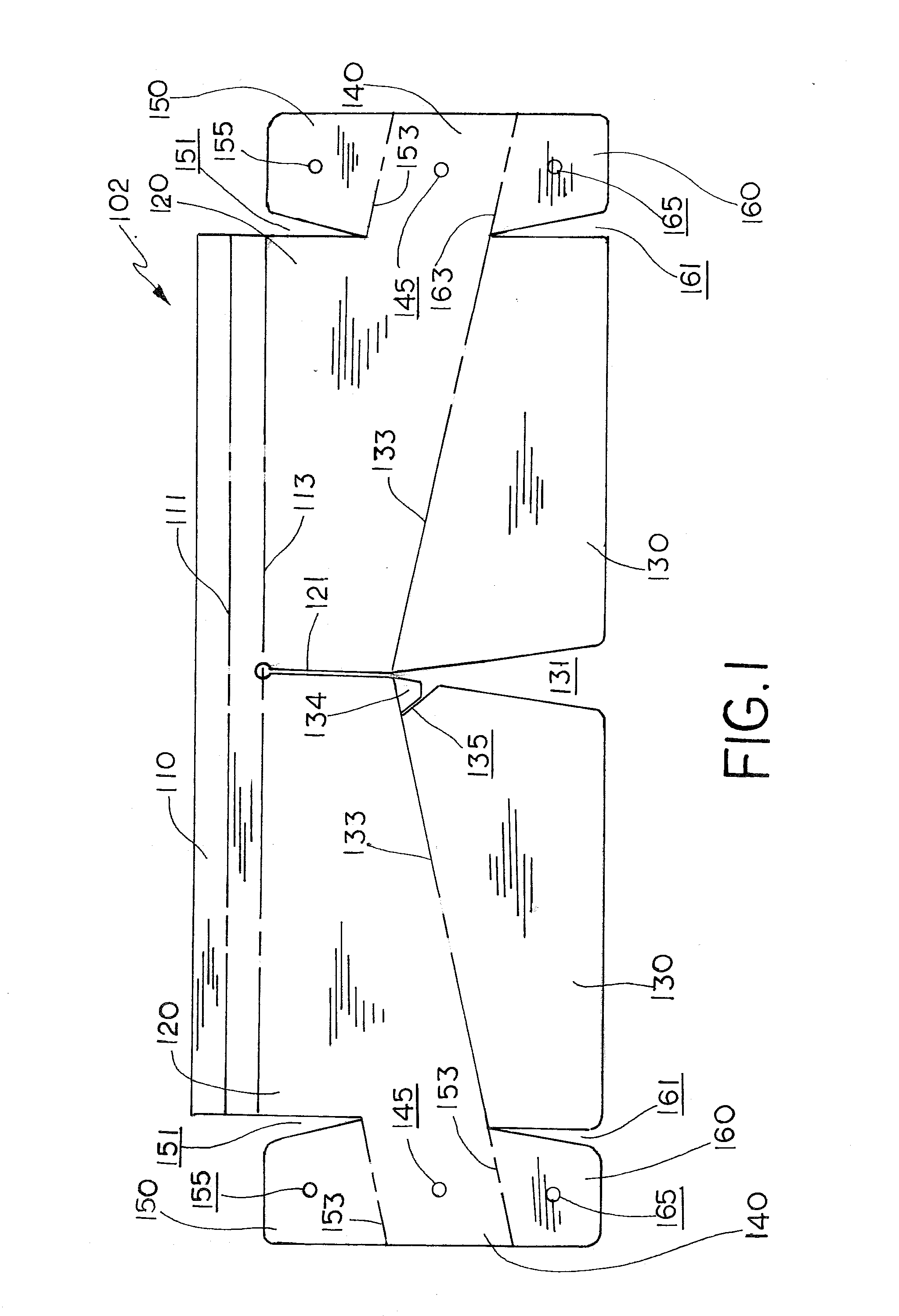
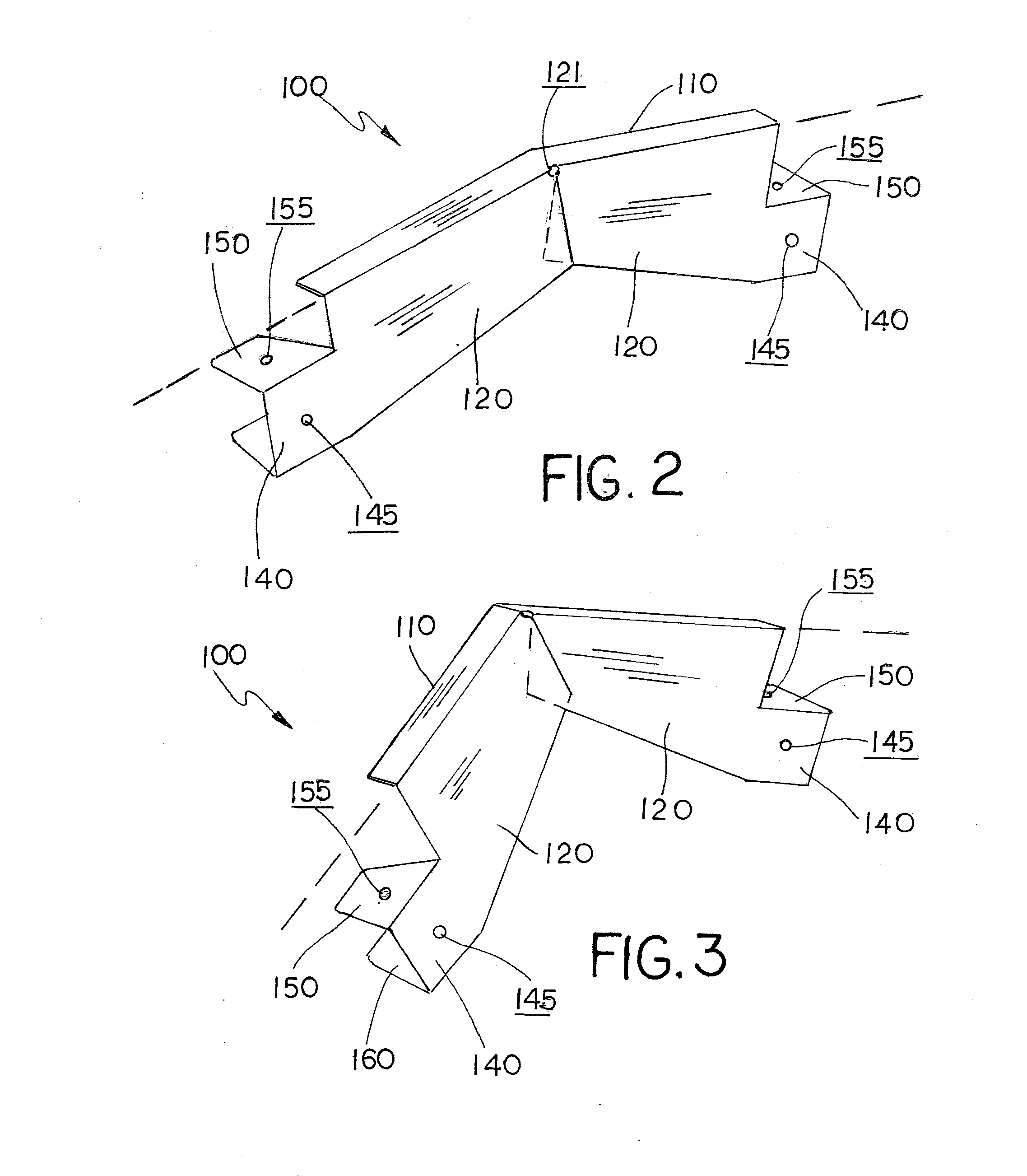
The invention is a ridge vent end cap that can be easily bent to fit roofs of varying pitches while enclosing ridge vents of various styles. The end cap has preformed key hole slots that allow it to bend without buckling and conform to the pitch of the roof. The bent finished end cap has top ridge beam and a pair of end panels, bottom flaps, and corner flaps with tooth-like elements to prevent picing or burrowing by rodents and insects. The invention simplifies the process of installing ridge vents on roofs and reduces the risk of animals entering the building.

Problems solved by technology

End caps fashioned and bent to enclose a particular ridge vent mounted to one roof will not adequately enclose or seal the end opening of the same ridge vent on a roof having a different pitch.

Method used


Image

  • Ridge Vent Cap
  • Ridge Vent Cap
  • Ridge Vent Cap

Examples


Embodiment Construction

[0020]In the following detailed description of the preferred embodiments, reference is made to the accompanying drawings that form a part hereof, and in which is shown by way of illustration specific preferred embodiments in which the invention may be practiced. These embodiments are described in sufficient detail to enable those skilled in the art to practice the invention, and it is understood that other embodiments may be utilized and that logical, structural, mechanical, electrical, and chemical changes may be made without departing from the spirit or scope of the invention. To avoid detail not necessary to enable those skilled in the art to practice the invention, the description may omit certain information known to those skilled in the art. The following detailed description is, therefore, not to be taken in a limiting sense, and the scope of the present invention is defined only by the appended claims.

[0021]Referring now to the drawings, FIGS. 1-4 illustrate an embodiment of...


PUM


Abstract

A ridge vent end cap that can be readily bent to conform to roofs of varying pitches while enclosing ridge vents of various styles. The end caps are bent and fashioned for a flat blank, which is configured to allow it to be bent and formed into a shape that accommodates various styles of ridge vents and that encloses ridge vents on roofs with varying pitches. The bent finished end cap has a top ridge beam and a pair of end panels, bottom flaps and corner flaps. Each corner flap has its own top corner flap and a bottom corner flap. A preformed key hole slot along the central axis / plane of the blank or finished end cap allows the end cap to bend without buckling so that the end panels slide over one another to enclose the end open of the ridge vent while conforming to the pitch of the roof. A tooth is formed in one of the bottom flaps, which bites into the roof shingles helps ensure that the end panels cannot be pried up or burrowed under by rodents and insects.

Description

[0001]This invention relates to ridge vents for sloped roofs, and in particular ridge vent end caps that can conform to sloped roofs of varying pitches.BACKGROUND AND SUMMARY OF THE INVENTION[0002]Ridge vents are a type of vent installed at the peak of a sloped roof which allows warm, humid air to escape a building's attic. Ridge vents are most common on shingled residential buildings. Ridge vents allow warm air to flow through from attics during summer months to cool the building to reduce cooling costs. During winter months, these vents allow moisture to escape attics, which prevents the deterioration of attic insulation. While roof ridge vents help maintain the climate within the attics, they allow provide a point of egress for small animals to enter the building.[0003]Typically, end caps are fashioned and bent from metal flashing and scrap pieces of sheet metal to enclose the ends of roof ridge vents. While most type of ridge vent can be readily adapted for use on roofs of diffe...

Claims


Application Information

Patent Timeline
IPC IPC(8): F24F13/20
CPCF24F13/20E04D13/174F24F7/02
Inventor STOUFFER, JOHN D.
Owner STOUFFER TECH
Learn More