Axial flow pump pressure algorithm

Active Publication Date: 2014-12-04
HEARTWARE INC
View PDF1 Cites 94 Cited by
  • Summary
  • Abstract
  • Description
  • Claims
  • Application Information

AI Technical Summary

Benefits of technology

[0013]Yet another aspect of the disclosure provides for an implantable blood pump system including a pump, rotor and control circuit operatively coupled to the pump and configured to: determine a differential pressure across the blood pump based at least in part on an initial speed of rotation of the rotor; compare the differential pressure to a threshold pressure value; determine the presence or absence of a high pressure condition based at least in part on the comparison; and in response to determining the presence of a high pressure condition, determine an updated speed of rotation of the rotor, the updated speed being less than the initial speed. In one example, the control circuit may further be operative to determine differential pressure based further on a flow rate of blood. In another example, the control circuit may further include a pump control module operative to control operation of the pump based on the updated determined speed. In a further example, the control circuit may include a processor coupled to a memory, the memory storing one or more tables, the one or more tables relating flow rates to corresponding differential pressure values for a given speed of rotation of the rotor, wherein at least one table relates flow rates to differential pressure values at the initial speed. In yet another example, the control circuit may be operative to determine the updated speed based on the speed of the rotor at which the presence of a high pressure condition is determined.
[0014]In some examples, the control circuit may also determine differential pressure across the blood pump at the updated speed, and may further be operative to delay such determination for a predetermined amount of time based on a count value indicative of a number of recovery attempts initiated.
[0015]Yet a further aspect of the disclosure provides for a control circuit for monitoring the operation of an implantable blood pump. The control circuit may include a differential pressure determination circuit, a pressure condition determination circuit, and an operating speed determination circuit, the operating speed determination circuit operative to determine a reduced speed of rotation of the rotor based on the determination of the pressure condition determination circuit. In some examples, the control circuit may further include a flow rate determination circuit operative to determine a flow rate of blood, and a flow recovery determination circuit operative to determine whether the determined flow rate of blood is at least equal to a flow recovery threshold value. In such examples, the operating speed determination circuit may be further op

Problems solved by technology

This increase of differential pressure may be harmful to the patient, and m

Method used


Image

  • Axial flow pump pressure algorithm
  • Axial flow pump pressure algorithm
  • Axial flow pump pressure algorithm

Examples


Embodiment Construction

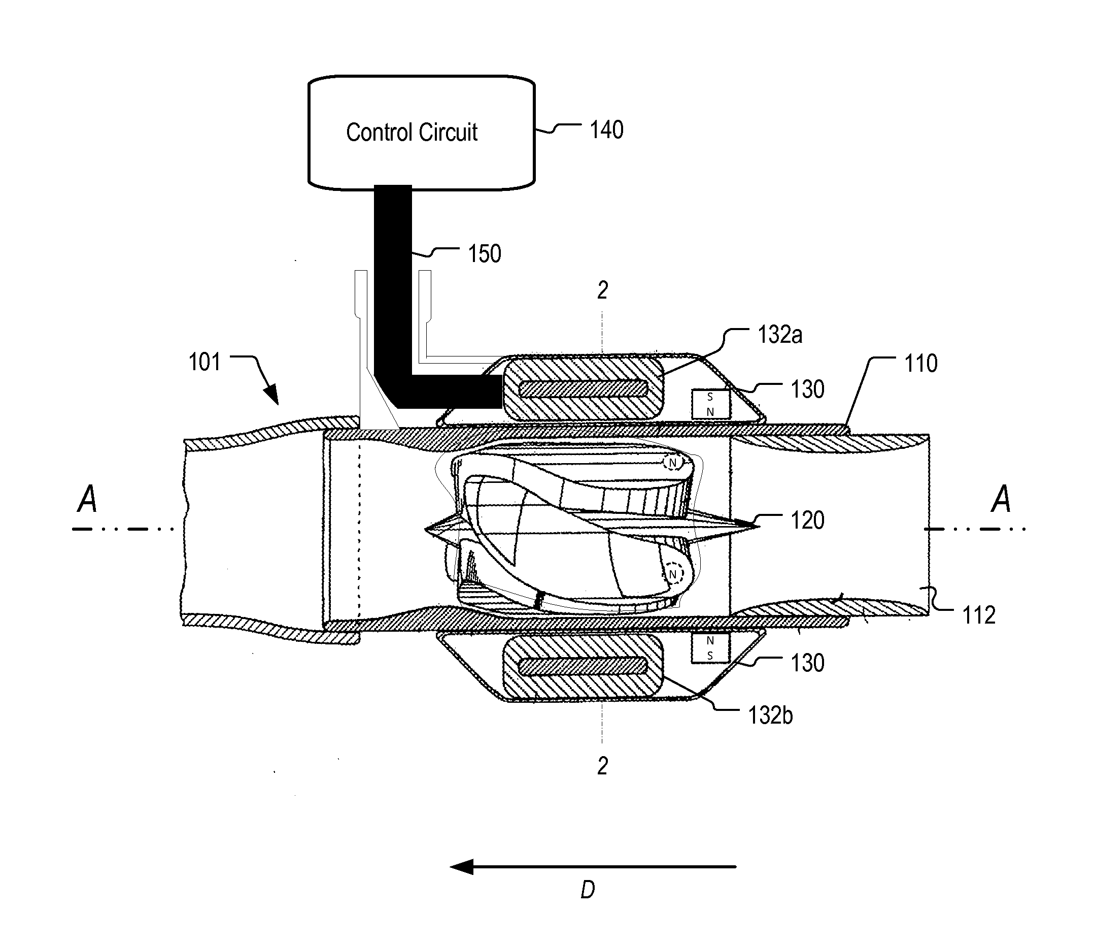
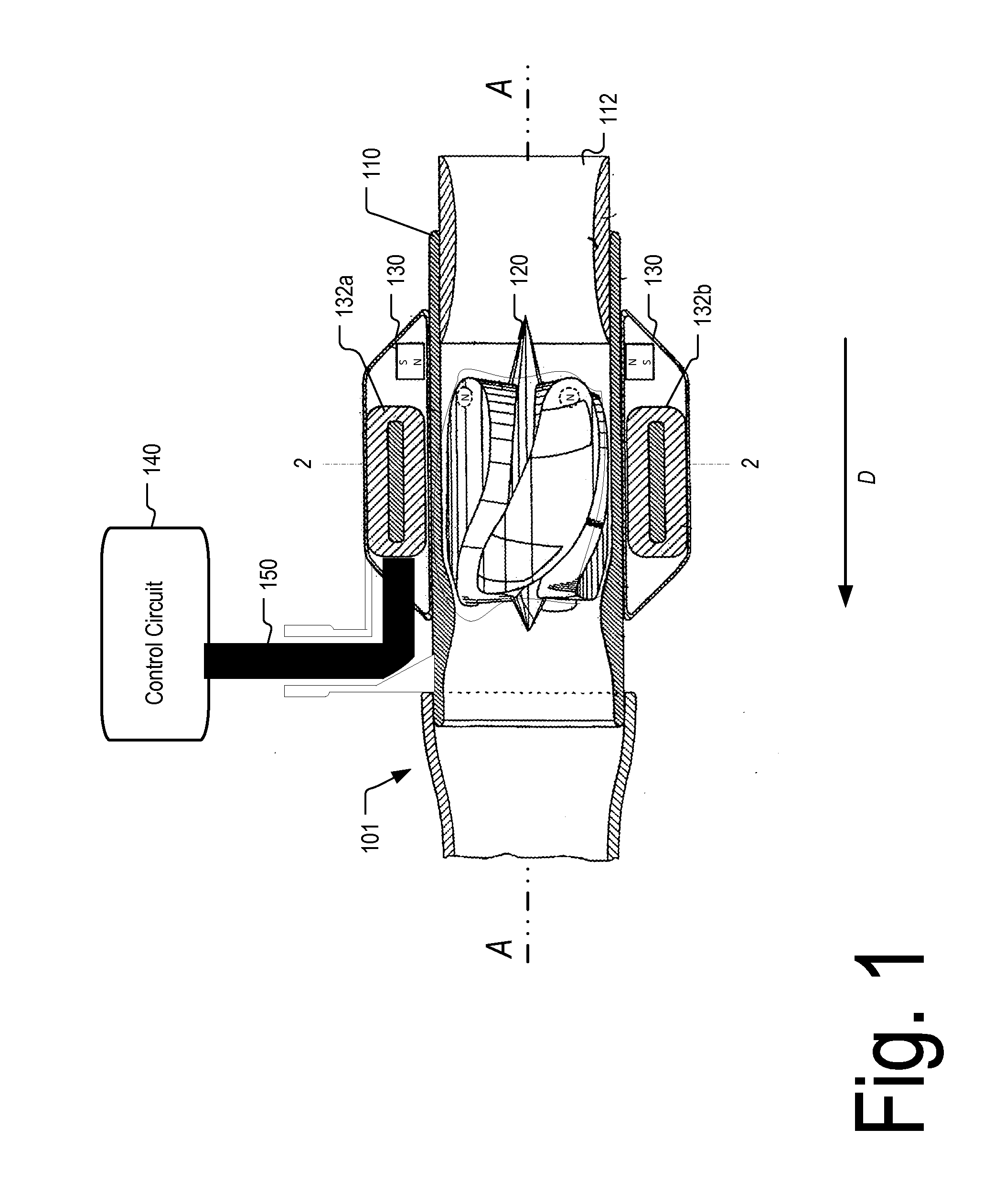
[0031]FIGS. 1-3 depict a blood pump system 100 in accordance with one embodiment of the invention. The blood pump system 100 according to this embodiment includes a control circuit 140 connected via a cable feed 150 to a blood pump 101. The blood pump 101 includes a housing 110 defining a bore 112 having an axis A. A rotor 120 is disposed within the bore. The rotor 120 has a permanent magnetization with flux direction perpendicular to the axis of the bore. The rotor constitutes an impeller configured to push blood in a downstream direction D parallel to the bore 112 when the rotor is turning.

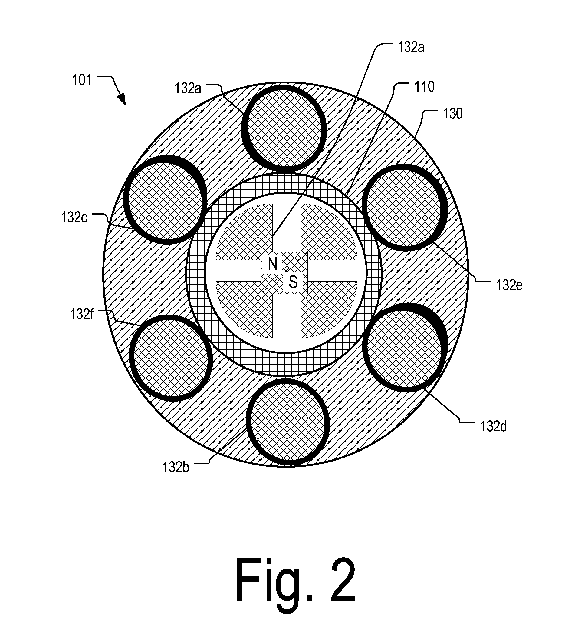
[0032]The pump also includes a stator 130. The stator includes coils 132a-e (FIG. 2) connected in a WYE or delta configuration and placed around the circumference of the housing 110. The coils are arranged in pairs diametrically opposed to one another. Thus, coils 132a and 132b form one pair, coils 132c and 132d form another pair, and coils 132e and 132f form another pair. When the coils are dri...


PUM


Abstract

The presence or absence of a high pressure condition in an implantable blood pump is determined at least in part based on a comparison between a determined amount of differential pressure across the pump and a pressure threshold value. The amount of differential pressure parameter may be determined based at least in part on a parameter related to flow, such as a parameter related to thrust on the rotor of the pump. In response to determining the presence of a high pressure condition, an updated speed of rotation of the rotor that is less than the rotor's initial speed may be determined. The rotor's speed may be increased when the flow rate of blood is determined to be at least equal to a flow recovery threshold value.

Description

CROSS-REFERENCE TO RELATED APPLICATIONS[0001]The present application claims the benefit of the filing date of U.S. Provisional Patent Application No. 61 / 831,023 filed Jun. 4, 2013, the disclosure of which is hereby incorporated herein by reference.FIELD OF THE INVENTION[0002]The present invention relates to blood pumps, to methods of using blood pumps, and to control circuits adapted for use with blood pumps.BACKGROUND OF THE INVENTION[0003]Implantable blood pumps may be used to provide assistance to patients with late stage heart disease. Blood pumps operate by receiving blood from a patient's vascular system and impelling the blood back into the patient's vascular system. By adding momentum and pressure to the patient's blood flow, blood pumps may augment or replace the pumping action of the heart. For example, a blood pump may be configured as ventricular assist device or “VAD.” Where a VAD is used to assist the pumping action of the left ventricle, the device draws blood from th...

Claims


Application Information

Patent Timeline
IPC IPC(8): A61M1/10A61M1/12
CPCA61M1/125A61M1/1086A61M2205/3334A61M60/422A61M60/148A61M60/546A61M60/237A61M60/178A61M60/538A61M60/531A61M60/585
Inventor REYES, CARLOSCASAS, FERNANDOWOLMAN, JUSTIN
Owner HEARTWARE INC
Why Eureka
Try Eureka