Vibration damper with a hydraulic end stop

Active Publication Date: 2014-12-11
ZF FRIEDRICHSHAFEN AG
View PDF2 Cites 20 Cited by
  • Summary
  • Abstract
  • Description
  • Claims
  • Application Information

AI Technical Summary

Benefits of technology

[0012]In a further advantageous embodiment, a supporting surface is constructed as an annular groove at the piston rod. When the axial extension of the annular groove is greater than the height of the spring tongues, the sealing ring can slide along the annular groove in direction of the closure element when leaving the end stroke region of the piston, can lift from the end stop ring and can release the flow of damping medium from the first working chamber into the control chamber.
[0013]When the sealing ring has at least one outer bevel which is formed, for example, at the side remote of the end stop ring in the installed condition, a tilting of the control ring can be prevented during penetration into the control tube. It is also advantageous for this purpose to form the outer bevel of the sealing ring at the side remote of the end stop ring in the installed condition. For the same purpose, the control tube can advantageously have an inner bevel at its end remote of the fastening portion.
[0014]To increase the flexibility of the sealing ring, the sealing ring can be formed with interruptions in its circumference. This better compensates for deviations in geometry and a possible radial offset. According to a further advantageous embodiment, the widening of the sealing ring in cir

Problems solved by technology

For reasons relating to comfort, the damping force of a vibration damper cannot be increased to any desired level.
Therefore, the damping force is not always su

Method used


Image

  • Vibration damper with a hydraulic end stop
  • Vibration damper with a hydraulic end stop
  • Vibration damper with a hydraulic end stop

Examples


Example

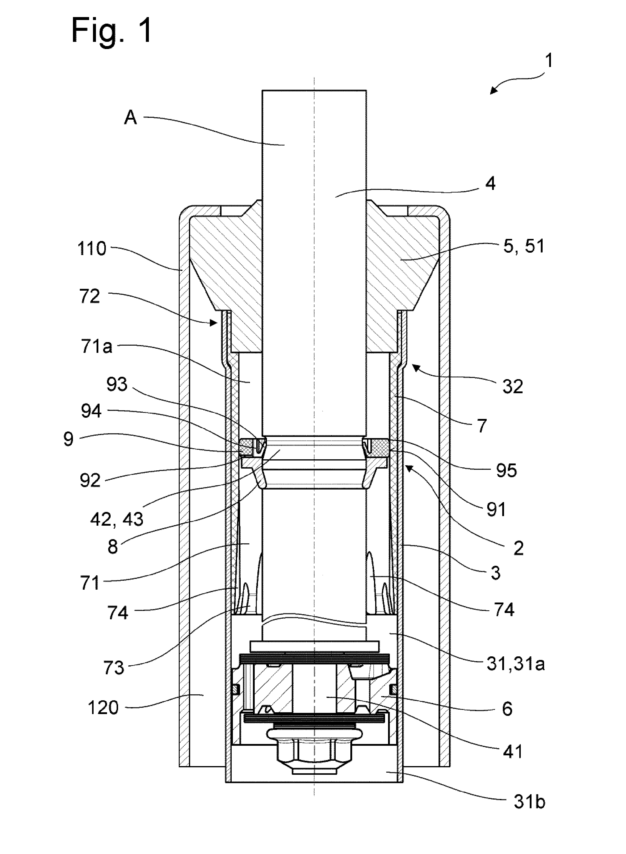
[0026]FIGS. 1 and 4 show a constructional embodiment of the vibration damper 1 with a hydraulic end stop 2 according to the invention, wherein the latter is constructed as an extension stop. An embodiment as compression stop is not shown separately in the drawings but is, of course, also possible.

[0027]The vibration damper 1 shown in FIG. 1 is a twin-tube damper and comprises a cylinder 3 which is enclosed by an outer tube 110. The cylinder space 31 is completely filled with a liquid damping medium. A compensation space 120 which is filled with a definite amount of damping medium is radially defined between the outer tube 110 and the cylinder 3. The remaining volume of the compensation space 120 is filled with gas. The cylinder space 31 and the compensation space 120 are connected by a bottom valve, not shown, which defines the flow of damping medium between the two spaces. However, application of the present invention cannot be limited only to a twin-tube damper. On the contrary, i...


PUM


Abstract

The vibration damper including a hydraulic end stop that has a sealing ring which is arranged between the end stop ring and the closure element, is supported axially on one side at the end stop ring, engages radially around the piston rod, is mounted in a sliding manner at the piston rod, and with its outer circumferential surface radially contacts the inner wall of the control space, wherein the sealing ring has at least one radial throttle groove which takes effect when the end stop with the sealing ring moves into the control space and ensures a defined flow of damping medium between the control chamber and the first working space, and wherein the sealing ring has a plurality of spring tongues which are supported at a supporting surface on the piston rod side.

Description

FIELD OF THE INVENTION[0001]The present invention is directed to a vibration damper with a hydraulic end stop.BACKGROUND OF THE INVENTION[0002]Vibration dampers with hydraulic end stops have been used for many years in the automotive industry. For reasons relating to comfort, the damping force of a vibration damper cannot be increased to any desired level. Therefore, the damping force is not always sufficient to damp body movements under extreme roadway stimuli. As a result, the axle and vibration damper can move into the rebound limit at high speed. Resilient end stops of elastic material are usually used for absorbing impact energy. However, the energy absorption of these parts is severely limited depending on the material used. On the other hand, hydraulically acting end stops are capable of absorbing appreciably higher impact energy.[0003]U.S. Pat. No. 4,345,748 describes a vibration damper with a mechanical-hydraulic end stop. The mechanical-hydraulic end stop disclosed therein...

Claims


Application Information

Patent Timeline
IPC IPC(8): F15B15/24
CPCF15B15/24F16F9/49F16J15/16F15B15/222
Inventor BAALMANN, HELMUTSCHMITT, STEFANSCHMITT, PETER
Owner ZF FRIEDRICHSHAFEN AG
Why Eureka
Try Eureka