Method of Error Correction for 3D Imaging Device

a technology of imaging device and error correction, which is applied in the field of imaging device error correction, can solve problems such as increasing the signal-to-noise ratio, affecting the reliability and therefore usability of technology, and affecting the accuracy of imaging results

Active Publication Date: 2014-12-11
HAND HELD PRODS
View PDF4 Cites 694 Cited by
  • Summary
  • Abstract
  • Description
  • Claims
  • Application Information

AI Technical Summary

Problems solved by technology

Although there is tremendous potential for range imaging devices in a variety of commercial and research sectors, there remain challenges to the reliability, and therefore usability, of the technology.
For example, external factors that interfere with the detection of light reflected back to the range imaging camera can contribute to errors in distance measurement.
Background light (e.g., ambient light) can reach the pixels, thereby increasing the signal-to-noise ratio and diminishing the ability of the pixel to obtain an accurate determination of the light beam's travel time.
Similarly, interference problems can result when multiple range imaging cameras are in use at the same time, which c...

Method used


Image

  • Method of Error Correction for 3D Imaging Device
  • Method of Error Correction for 3D Imaging Device
  • Method of Error Correction for 3D Imaging Device

Examples


Embodiment Construction

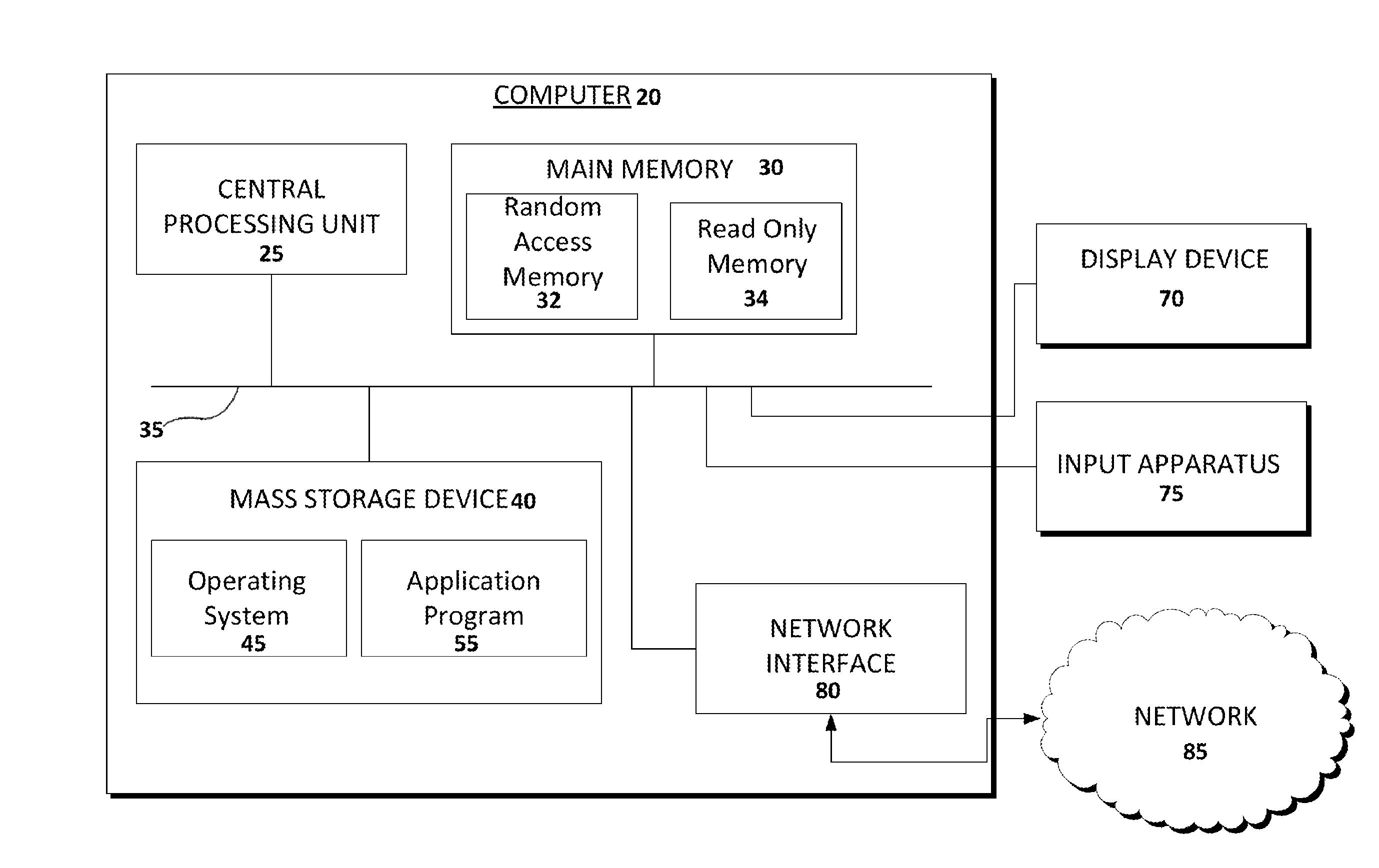
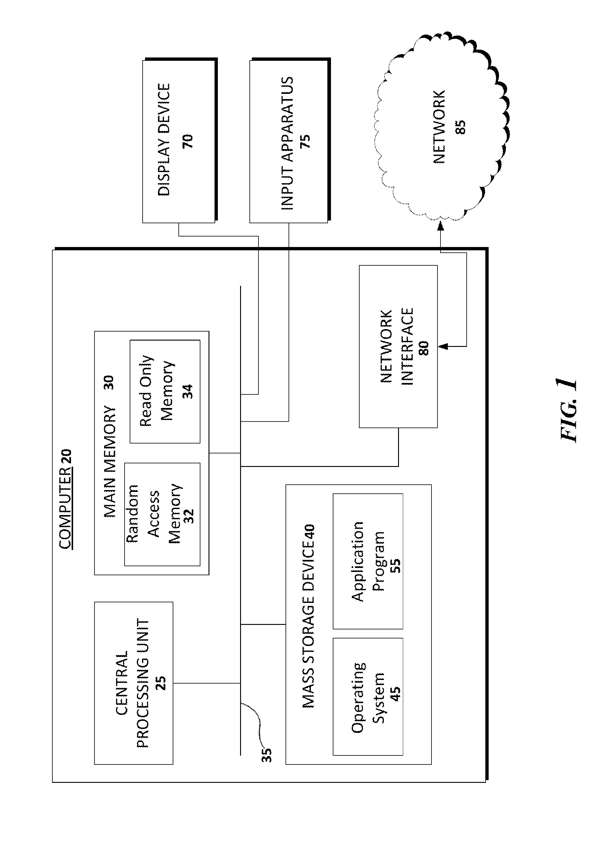
[0017]Turning now to the drawings, FIG. 1 is a schematic block diagram of an exemplary computer 20 used in an exemplary method according to the present disclosure. The computer 20 is used to calculate and compile errors in measurement by the 3D scanner, and to apply error correction calculations, as appropriate, to measurements received by the computer 20 from the 3D scanner. The computer 20 includes a mass storage device 40 for storing an operating system 45 and application programs 55. The mass storage device 40 may store other types of information. The operating system 45 is software that controls the overall operation of the computer 20, including process scheduling and management, process protection, and memory management. Examples of a suitable operating system include, without limitation, WINDOWS® 7 from MICROSOFT® CORPORATION of Redmond, Wash., and the LINUX® open source operating system. Typically, the operating system 45 is loaded by booting the computer 20 and is executed...


PUM


Abstract

A method is presented for correcting errors in a 3D scanner. Measurement errors in the 3D scanner are determined by scanning each of a plurality of calibration objects in each of a plurality of sectors in the 3D scanner's field of view. The calibration objects have a known height, a known width, and a known length. The measurements taken by the 3D scanner are compared to the known dimensions to derive a measurement error for each dimension in each sector. An estimated measurement error is calculated based on scans of each of the plurality of calibration objects. When scanning target objects in a given sector, the estimated measurement error for that sector is used to correct measurements obtained by the 3D scanner.

Description

FIELD OF THE INVENTION[0001]The disclosure relates generally to imaging devices, and, more particularly, to a method of error correction for an imaging device.BACKGROUND OF THE DISCLOSURE[0002]Many commercial and research sectors have a need for rapid three-dimensional (3D) measurements of objects. Recently, 3D range cameras (e.g., laser range cameras (LRC), range imaging cameras, range cameras, 3D cameras, time-of-flight cameras, ToF cameras) have gained in popularity due to certain advantages over other types of 3D dimensioning systems such as laser scanners (e.g., LIDAR), and due to advances in technology making the use of 3D range cameras more practical. Range imaging cameras resolve distance based on the known speed of light using a time-of-flight technique. An illumination unit such as a laser or LED array illuminates the field of view. The reflected light is gathered by optics onto an image sensor (e.g., CCD, CMOS). Each collector (e.g., pixel) of the image sensor simultaneou...

Claims


Application Information

Patent Timeline
IPC IPC(8): H04N13/04G01S17/894
CPCH04N13/0425G01S7/497G01S17/894
Inventor JOVANOVSKI, BRIAN L.LI, JINGQUAN
Owner HAND HELD PRODS
Why Eureka
Try Eureka