Headlight system incorporating adaptive beam function

a headlight system and beam function technology, applied in the field of light source systems, can solve the problems of reducing the optical efficiency of the projector headlight, unable to modify the output from the source, and creating a restricted view

Active Publication Date: 2014-12-11
SHARP KK
View PDF10 Cites 75 Cited by
  • Summary
  • Abstract
  • Description
  • Claims
  • Application Information

AI Technical Summary

Benefits of technology

[0053]A first aspect of the invention provides a light source system operable in at least first and second modes to provide at least and first and second different far field illumination patterns, the system comprising: a photoluminescent material; and a light beam generator for generating at least two independently controllable sets of light beams for illuminating respective regions of the photoluminescent material; wherein the light beam generator comprises at least one semiconductor light emitting device spatially separated from the photoluminescent material. By causing the generating means to generate one set of light beams so as to illuminate one region of the photoluminescent material, the one region of the photoluminescent material is caused to emit visible light and thus generate one far field illumination pattern, whereas causing the generating means to generate another set of light beams so as to illuminate another region of the photoluminescent material, the another region of the photoluminescent material is caused to emit visible light and thus generate another far field illumination pattern. By specifying that the sets of light beams are independently controllable is meant that the intensity of light beams of one set is controllable independently of the intensity of light beams of the other set. (It should be noted that the region of the photoluminescent material that is illuminated by one set of light beams may or may not overlap the region of the photoluminescent material that is illuminated by another set of light beams.)
[0054]The photoluminescent material may be a fluorescent material, such as a fluorescent phosphor.
[0055]For the avoidance of doubt, the term “phosphor” as used herein includes a nanophosphor.
[0056]To the accomplishment of the foregoing and related ends, the invention, then, comprises the features hereinafter fully described and particularly pointed out in the claims. The following description and the annexed drawings set forth in detail certain illustrative embodiments of the invention. These embodiments are indicative, however, of but a few of the various ways in which the principles of the invention may be employed. Other objects, advantages and novel features of the invention will become apparent from the following

Problems solved by technology

By necessity, the dipped beam also creates a restricted view of the road due to restricted illumination of the same.
The removal of light is performed by a shield, which is inserted into the light path thereby causing a reduction in optical efficiency of the projector headlight.
The filament and discharge light sources provide no means for modification of the output from the source.
The provision of only a dipped beam distribution, or of only a driving beam distribution, has limitations in terms of road user safety by not providing simultaneous optimal illumination of the road and minimal glare to other road users.
However, all methods of creating an adaptive beam spot from a single projector unit require mechanical moving components within the headlight unit.
This has a limitation on cost reduction and reliability of the headlight over the course of its lifetime.
Alternative methods of provision of an adaptive beam spot require multiple light source units, which increases the headlight cost, and which also have a large volume, this having implications for pedestrian safety in the event of a collision.
In one embodiment three separate light sources are provided to provide increased output intensity, but these light sources cannot be operated independently from one another.
Furthermore, the phosphor surface is collinear with the optical axis, resulting in poor reproduction of any distribution upon the phosphor in the far field.
It is however not possible to vary the output illumination pattern.

Method used


Image

  • Headlight system incorporating adaptive beam function
  • Headlight system incorporating adaptive beam function
  • Headlight system incorporating adaptive beam function

Examples


Embodiment Construction

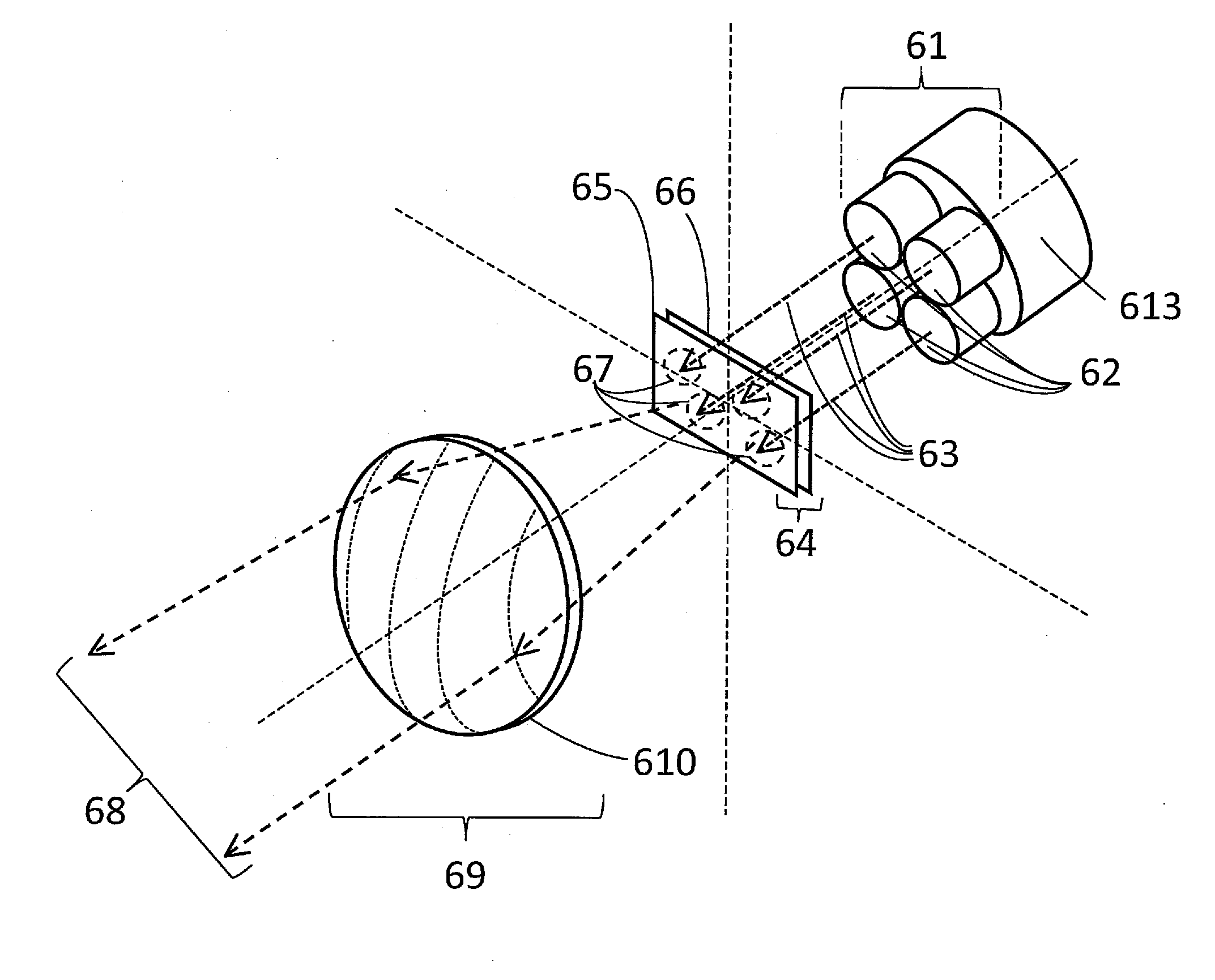
[0104]The main embodiment of the present invention is described herein and an overview of the same is presented in FIG. 6a. A group of laser light sources 61 is comprised of an array of multiple individual laser emitters 62. The laser emitters 62 may be mounted on a heat sink 613 if necessary. From herein the heat sink 613 will be omitted from figures for clarity, but may always be associated with laser emitters 62 or a laser emitter array 61. The laser emitters 62 emit, in use, light beams 63 of a first waveband. The light beams 63 of the first waveband from the laser emitters 62 are directed onto a light source 64 comprising a fluorescent material 65 which it deposited onto a substrate 66. From herein the light source 64 will generally be shown as one object. The individual light beams 63 form an array of illumination spots 67 on the light source 64 which are distinct, but not necessarily separated from one another. The fluorescent material 65 converts the light of the first waveb...


PUM


Abstract

A light source system comprising projection optics, which are capable of producing a far-field image of a light source. The light source comprises a fluorescent medium that when illuminated by light from laser emitters of a first waveband emits light of a second or more wavebands of longer wavelength. The resulting light emission produces a colour perceived as white. The light source is illuminated by a plurality of laser emitters arranged to illuminate the light source in an array-like manner. Control of the output of one or more of the laser emitters results in a variation of the spatial emission distribution from the light source and hence a variation of the far-field beam spot distribution via non-mechanical means.

Description

TECHNICAL FIELD[0001]he present invention relates to a light source system that may, for example, be used in a headlight system for the provision of an illumination pattern on the road which may be adapted to best suit driving conditions. It also relates to a vehicle including such a headlight system.BACKGROUND ART[0002]The application of lighting to the automotive industry is well known. The original electric light sources were filament bulbs which offered high luminance from a small source. Improvements in light source design led to halogen type filament bulbs, high intensity discharge (HID) bulbs or high brightness light emitting diodes (LED). These offer improvement in terms of luminance and energy use over preceding filament bulbs. In order to apply these light sources to automotive front lighting and realise the beam spot distributions required by regulatory bodies, such as the United Nations Economic Commission for Europe (UNECE) or Federal Motor Vehicle Safety Standards (FMV...

Claims


Application Information

Patent Timeline
Patent Type & Authority Applications(United States)
IPC IPC(8): F21S8/10F21V13/14F21V8/00F21K99/00F21V13/02
CPCF21S48/1225F21K9/56F21S48/1747G02B6/0008F21V13/14F21V13/02B60Q2400/50F21W2111/02F21K9/64F21Y2115/10F21Y2115/30F21S41/14F21S41/143F21S41/153F21S41/16F21S41/176F21S41/24F21S41/285F21S41/60F21S41/657F21S41/663G02B6/4204G02B6/4216G02B6/4296H01S5/0071H01S5/4025H01S5/0087H01S5/02251B60Q1/076F21S41/141F21S41/18
Inventor SUCKLING, JAMES ROWLANDMONTGOMERY, DAVID JAMESTAKAHASHI, KOJI
Owner SHARP KK
Why Eureka
Try Eureka