Field assisted sintering of x-ray tube components

a technology of x-ray tube components and field assisted sintering, which is applied in the manufacture of x-ray tube targets, x-ray tube targets and convertors, electric discharge tubes/lamps, etc., can solve the problems of unreachable, inconvenient, and inherent drawbacks of production processes

Active Publication Date: 2014-12-11
GENERAL ELECTRIC CO
View PDF0 Cites 3 Cited by
  • Summary
  • Abstract
  • Description
  • Claims
  • Application Information

AI Technical Summary

Benefits of technology

[0010]According to another aspect of the invention, a method of fabricating an x-ray tube component useable in an x-ray tube includes providing a powder into an electrically conductive die, wherein the powder comprises one of a refractory metallic powder, a non-refractory metallic powder, and a ceramic powder, and wherein the die is constructed to have a cavity shaped as the x-ray tube component being fabricated. The method also includ

Problems solved by technology

Such production processes have inherent drawbacks that cannot be overcome—with such drawbacks including achievable material density and process cycle time, according to the specific process employed.
With respect to a PSF process, for example, the separate

Method used


Image

  • Field assisted sintering of x-ray tube components
  • Field assisted sintering of x-ray tube components
  • Field assisted sintering of x-ray tube components

Examples


Embodiment Construction

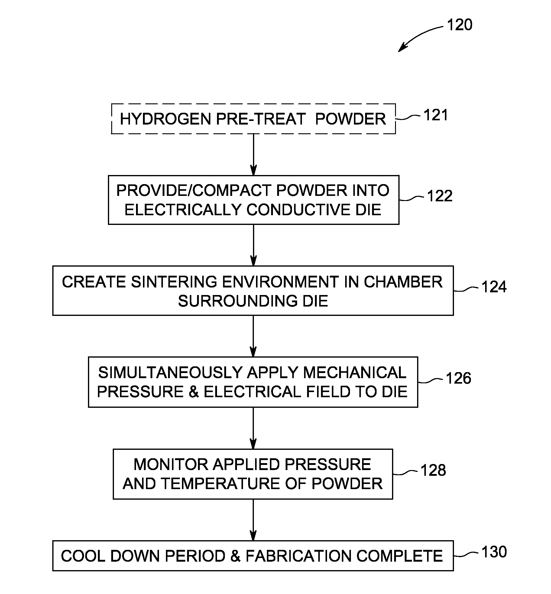
[0023]Embodiments of the invention are directed to a process for manufacturing x-ray tube components. A field-assisted sintering technology (FAST) process, also known as spark plasma sintering (SPS), is employed to generate x-ray tube components, with the FAST process providing for a reduced cycle time in manufacturing the component(s), and with the component(s) being provided as near-net-shape components and as full density / near-full density material components.

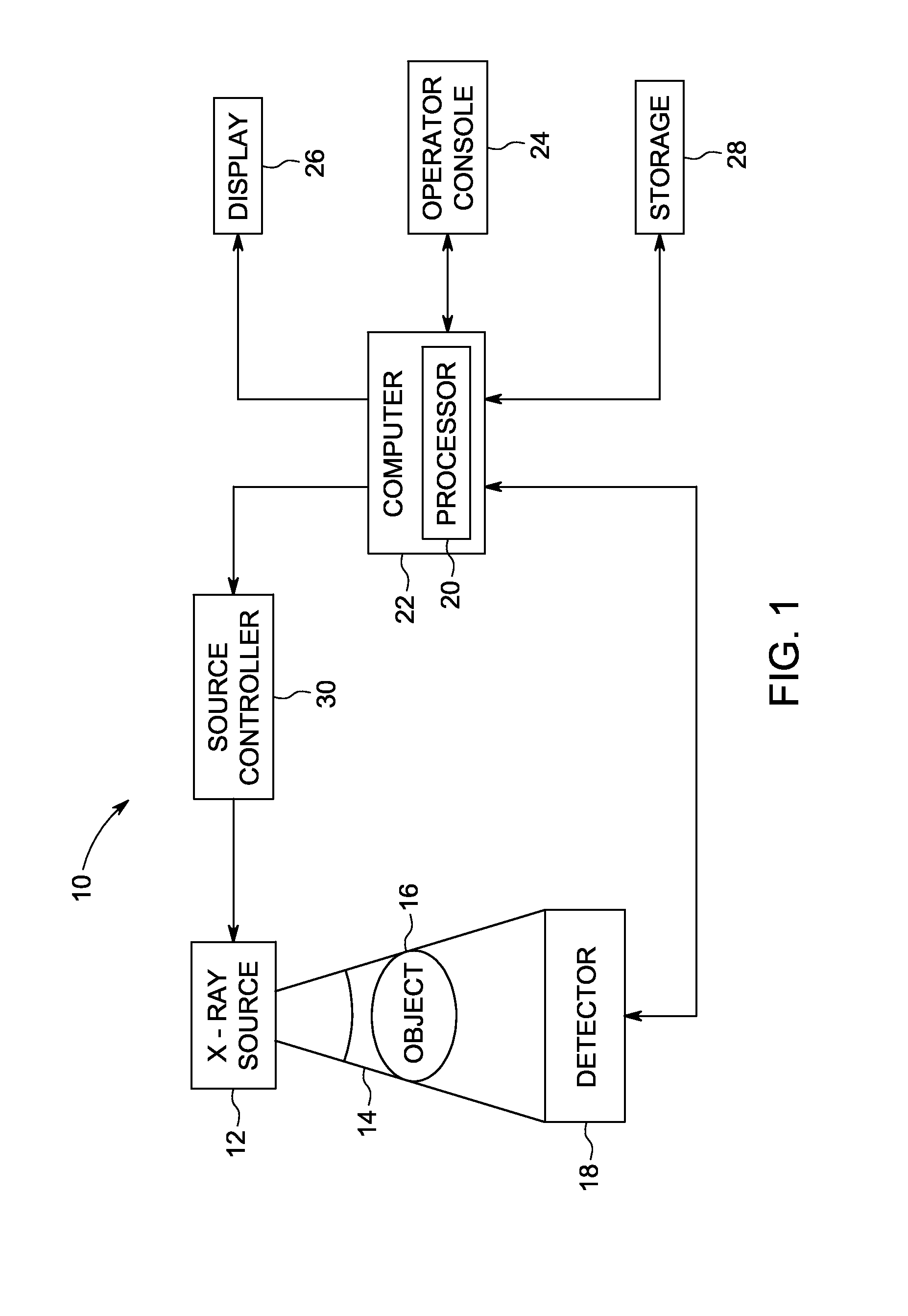
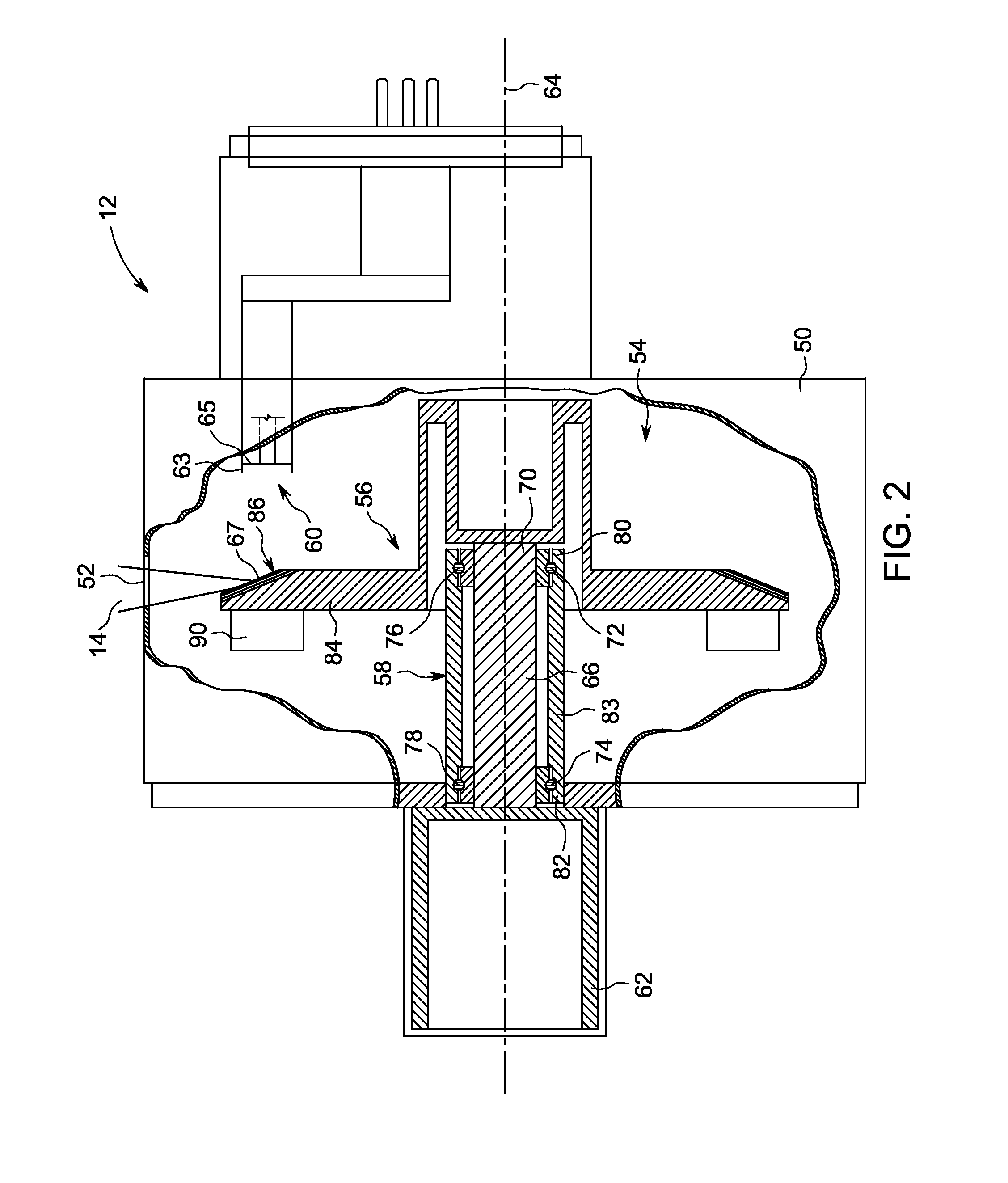
[0024]Referring to FIGS. 1 and 2 an imaging system 10 (FIG. 1) and associated x-ray tube 12 (FIG. 2) for use therein are shown that can benefit from incorporation of embodiments of the present invention. It will be appreciated by those skilled in the art that embodiments of the present invention are applicable to components for x-ray tubes of varying configurations, with the x-ray tube also being implementable with numerous medical imaging systems, such as a CT system, an x-ray system, a vascular system, and a mammography sy...


PUM


Abstract

A system and method for x-ray tube components is disclosed. The method of fabricating an x-ray tube component includes providing a powder into an electrically conductive die constructed to have a cavity shaped as the x-ray tube component being fabricated and simultaneously applying a mechanical pressure and an electric field to the die so as to cause sintering of the powder and thereby fabricate the x-ray tube component, wherein the electric field applied to the die directly passes through the die to the powder, so as to generate heat internally within the powder responsive to the applied electric field.

Description

BACKGROUND OF THE INVENTION[0001]Embodiments of the invention relate generally to x-ray tubes and, more particularly, to a method of fabricating x-ray tube components.[0002]Traditional x-ray imaging systems include an x-ray source and a detector array. X-rays are generated by the x-ray source, pass through an object, and are detected by the detector array. Electrical signals generated by the detector array are conditioned to reconstruct an x-ray image of the object.[0003]In general, the x-ray source is in the form of an x-ray tube that includes a vacuum housing enclosing an anode assembly and a cathode assembly. The cathode assembly includes an electron emitting filament that is capable of emitting electrons. The anode assembly provides an anode target that is spaced apart from the cathode and oriented so as to receive electrons emitted by the cathode. In operation, electrons emitted by the cathode filament are accelerated towards a focal spot on the anode target by placing a high v...

Claims


Application Information

Patent Timeline
IPC IPC(8): H01J35/08H01J9/14
CPCH01J35/08H01J2235/085H01J9/14H01J35/108
Inventor TIEARNEY, JR., THOMAS CARSONSTEINLAGE, GREGORY ALANROGERS, KIRK ALANPOQUETTE, BEN DAVID
Owner GENERAL ELECTRIC CO
Why Eureka
Try Eureka