Vibration damper with a hydraulic pressure stop

a technology of hydraulic pressure stop and vibration damper, which is applied in the direction of vibration damper, gas and liquid based damper, shock absorber, etc., can solve the problems of inability to adapt the damping force characteristic to a conventional passenger vehicle, the point at which the hydraulic pressure stop goes into action is easy to be detected, and the effect of this measure is limited

Inactive Publication Date: 2004-11-09
ZF SACHS AG
View PDF8 Cites 37 Cited by
  • Summary
  • Abstract
  • Description
  • Claims
  • Application Information

AI Technical Summary

Problems solved by technology

This damping force characteristic, however, cannot be usefully adapted to a conventional passenger vehicle.
That is, either both the damping force which occurs at low piston rod speeds and the maximum damping force in the desired range are too low, or the damping force is suitable at lower elastic travel speeds but much too high at faster piston speeds.
In applications in conventional passenger vehicles, furthermore, it is also disadvantageous that the point at which the hydraulic pressure stop goes into action can be easily detected.
Entrance grooves maybe made in the second piston to provide a bypass over a certain part of the distance traveled by the separating piston, but the effectiveness of this measure is limited.

Method used


Image

  • Vibration damper with a hydraulic pressure stop
  • Vibration damper with a hydraulic pressure stop
  • Vibration damper with a hydraulic pressure stop

Examples


Embodiment Construction

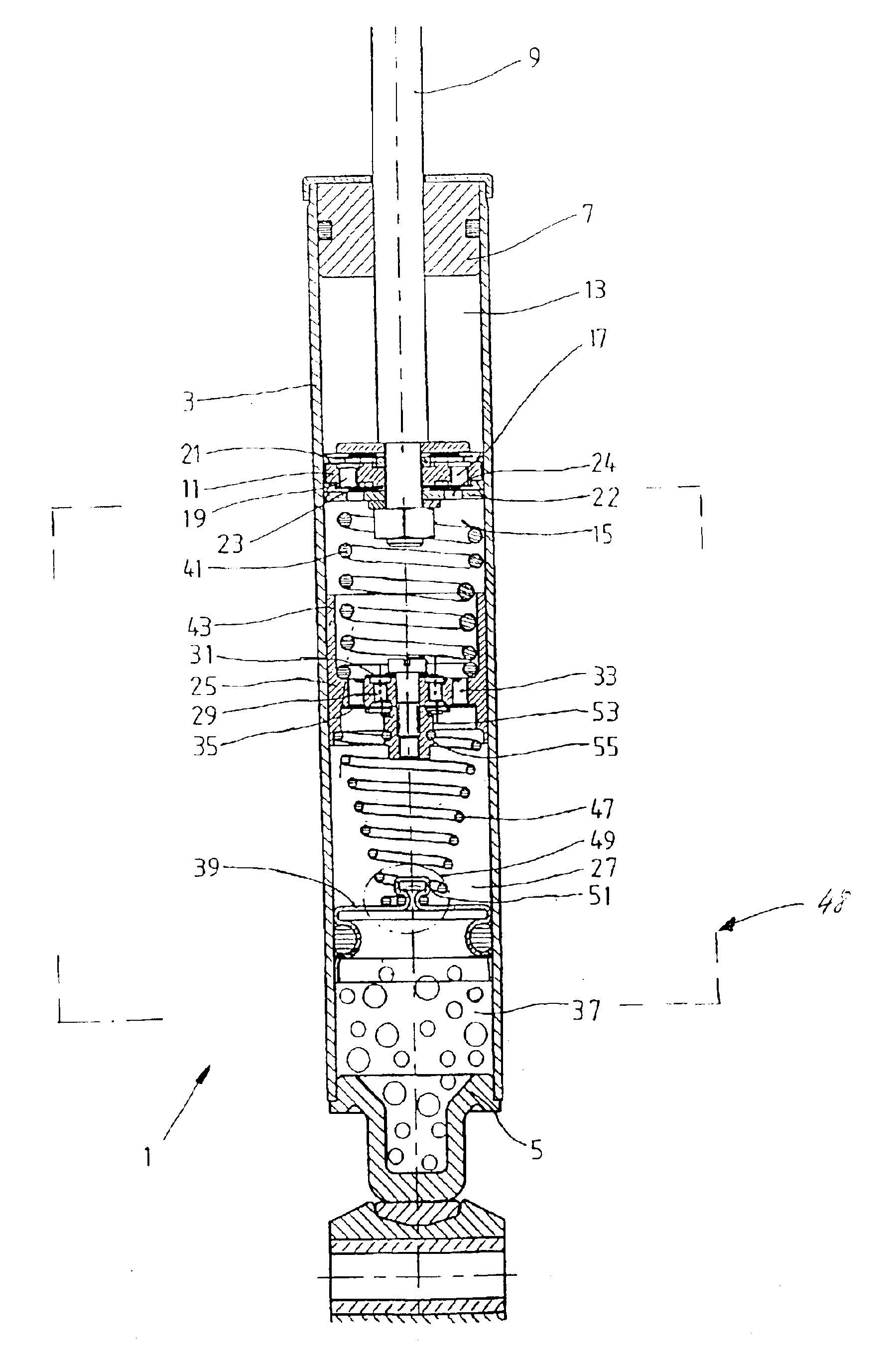
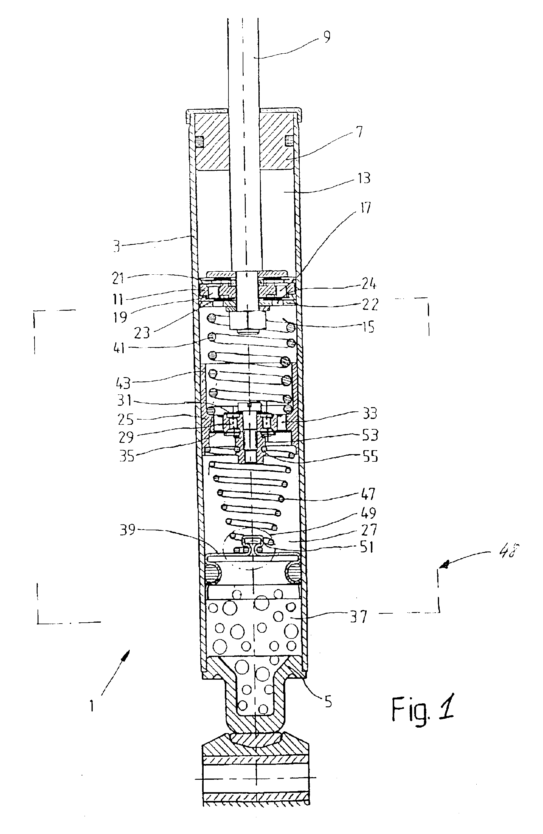
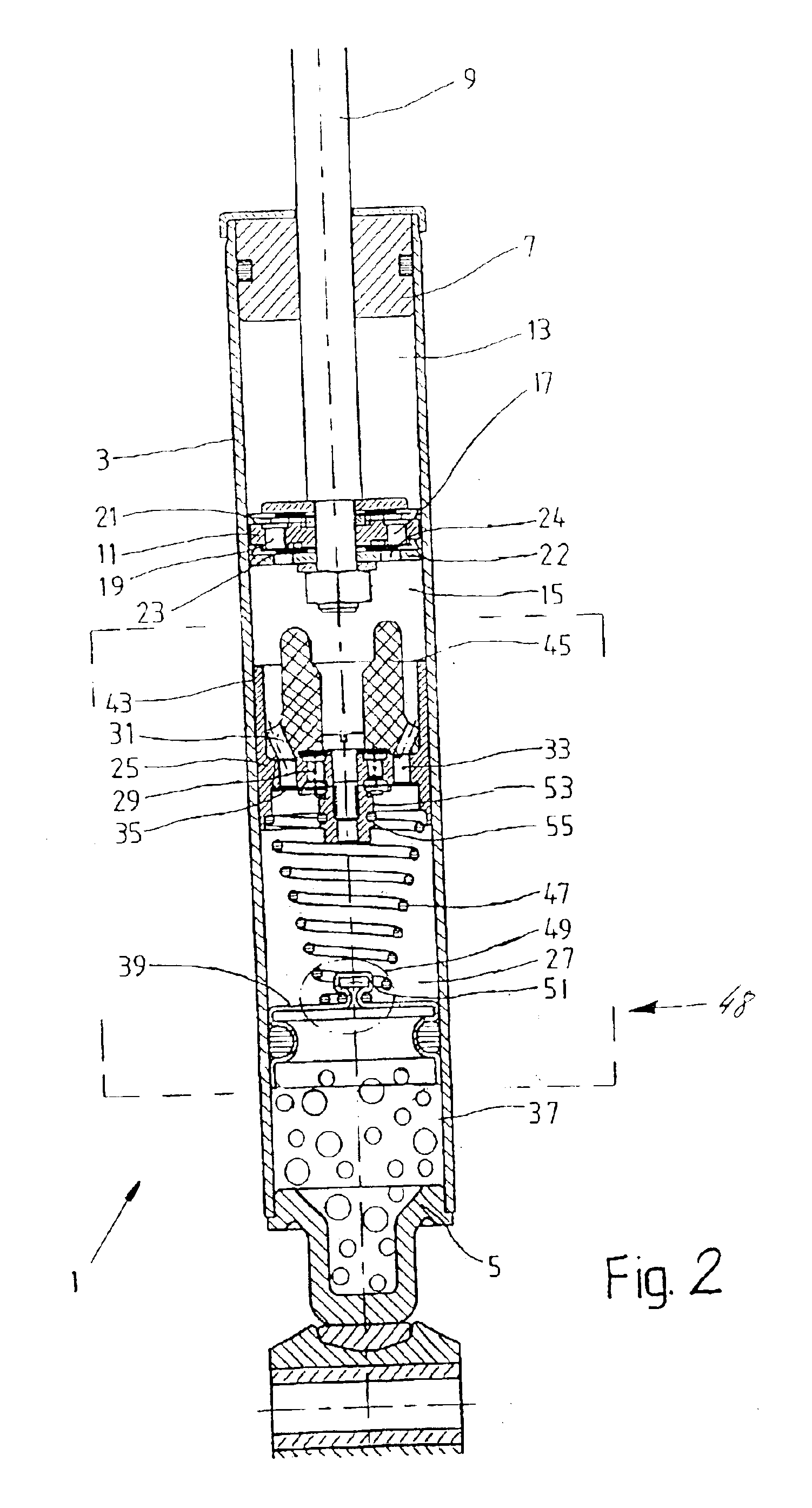
In FIGS. 1 and 2, a vibration damper 1 is a single-tube design, which has a cylinder 3 and which is closed off at the ends by a base piece 5 and a piston rod guide 7. The piston rod guide 7 centers an axially movable piston rod 9, to which a first piston 11 is attached. The first piston 11 separates a cylinder 3, which is filled with damping medium, into a first working space 13 and a second working space 15. Flow connections 17, 19 are provided inside the first piston 11, the outlets of which are covered alternately by at least one valve disk 21, 23. A support plate 22, which has non-throttling flow-through openings 24, is assigned at least to the valve disk 23 facing the second working space 15. When the piston rod a moves, the flow connections 17, 19 together with the valve disks 21, 23 generate a damping force regardless of whether the piston rod 9 is traveling inward or outward.

Between the base 5 and the first piston 11, a second piston 25 is installed with freedom of axial mov...


PUM


Abstract

A vibration damper with a hydraulic-mechanical pressure stop includes a cylinder filled with damping medium; a piston rod movable in and out of the cylinder, a first piston fixed to the piston rod with freedom of axial movement, a second piston spaced from the first piston, a transfer spring in the second working space for moving the second piston toward the third working space in response to movement of the first piston toward the second working space; and a disk valve which allows damping medium to flow from the third working space through the second piston to the second working space as the second piston moves toward the third working space. The first piston divides the cylinder into a first and a second working space where the piston rod extends through the first working space. The second piston separates the second working space from a third working space.

Description

1. Field of the InventionThe invention relates to a vibration damper with a pressure stop where the vibration damper includes a cylinder filled with a damping medium in which a piston rod together with a first piston is installed with freedom of axial movement and where the piston divides the cylinder into first and second working spaces.2. Description of the Related ArtA piston-cylinder assembly with a hydraulic-mechanical pressure stop is disclosed in known from DE 198 29 765 A1, which is hereby incorporated by reference in its entirety. Therein, a second piston is pushed by a rigid extension of the piston rod against a return spring as soon as the piston rod has traveled inward by a certain distance. The second piston is guided inside a pressure cylinder, which has a number of throttle connections leading to the adjacent working space and which is permanently supported on a valve body at the base of the vibration damper.During a normal inward travel phase, only the throttle conne...

Claims


Application Information

Patent Timeline
Patent Type & Authority Patents(United States)
IPC IPC(8): F16F9/00F16F9/48F16F9/49F16F9/06F16F9/50
CPCF16F9/061F16F9/50F16F9/49F16F9/067
Inventor GRUNDEI, MANFRED
Owner ZF SACHS AG
Why Eureka
Try Eureka