Load port unit and efem system

a technology of efem and load port, which is applied in the direction of transportation and packaging, conveyor parts, electric devices, etc., can solve the problems of nitrogen leakage outside the efem system, door does not have airtightness, etc., and achieves the effect of reducing the so-called takt time, increasing the supply of nitrogen, and increasing the probability of leakag

Active Publication Date: 2014-12-11
TDK CORPARATION
View PDF27 Cites 15 Cited by
  • Summary
  • Abstract
  • Description
  • Claims
  • Application Information

AI Technical Summary

Benefits of technology

[0006]In cases where the space inside a pod is purged with nitrogen when the lid of the pod is opened by a system disclosed in Japanese Patent No. 4301456 or 4309935, a simple way of and an important factor in reducing the so-called takt time is to increase the supply of nitrogen. However, a gap is provided between the door of the load port unit and wall having the opening portion through which the lid and wafers pass in order to prevent particles from entering the EFEM system. Moreover, the cover of the lid opening / closing mechanism having the door does not have airtightness in many cases. Therefore, if the supply of nitrogen is simply increased, it is probable that nitrogen leaks outside the EFEM system through such a gap or the like. The probability of leakage is considered to increase with an increase in the diameter of wafers. Therefore, solution to this problem is demanded in order to establish good working environment with EFEM systems.

Problems solved by technology

Moreover, the cover of the lid opening / closing mechanism having the door does not have airtightness in many cases.
Therefore, if the supply of nitrogen is simply increased, it is probable that nitrogen leaks outside the EFEM system through such a gap or the like.

Method used


Image

  • Load port unit and efem system
  • Load port unit and efem system
  • Load port unit and efem system

Examples


Embodiment Construction

[0016]Preferred embodiments of the present invention will now be described in detail in accordance with the accompanying drawings.

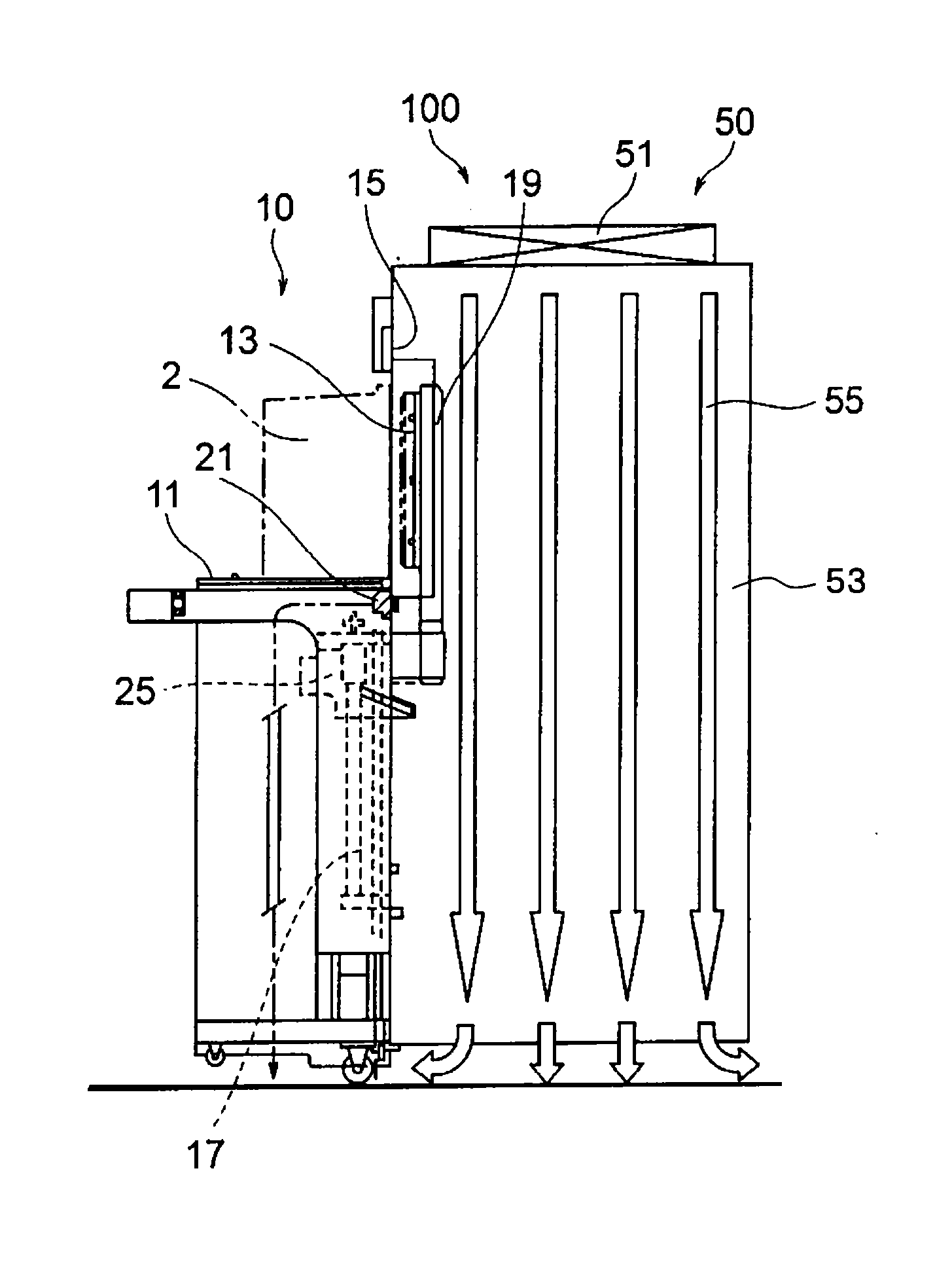
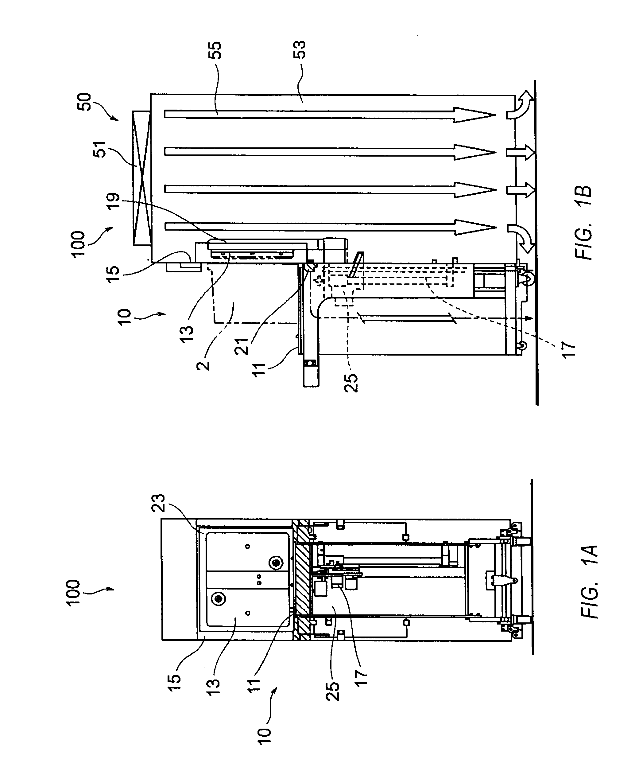
[0017]An embodiment of the present invention will be described with reference to the accompanying drawings. FIGS. 1A and 1B show the outer appearance of an EFEM system 100 according to an embodiment of the present invention. FIG. 1A is a view of the EFEM system 100 and a load port unit 10 as seen from front, and FIG. 1B is a view as seen from left side. The load port unit 10 includes a support table 11, a door 13, a closing plate 15, a door driving mechanism 17, an inert gas nozzle 19, and an air inlet unit 21. The EFEM system 100 includes an EFEM unit 50 that defines the aforementioned mini environment, a fan filter unit (which will be hereinafter referred to as FFU) 51, and the mini environment 53. The load port unit 10 is adapted to detach the lid of a pod 2, in which contents such as wafers are stored, to allow the wafers to be taken out from the pod ...


PUM


Abstract

A load port unit can prevent or control leakage of inert gas from an EFEM system to the outside. The load port unit used in the EFEM system is provided with an air inlet that opens on a side facing a mini-environment between the upper end of an opener driving unit and the lower end of the pod. The width of the air inlet opening is larger than the width of the opening of the pod. With this arrangement, surplus gas is sucked from the pod when gas purging is performed on the pod.

Description

BACKGROUND OF THE INVENTION[0001]1. Field of the Invention[0002]The present invention relates to what is called an equipment front end module system (which will be hereinafter referred to as an EFEM system), which is used in a semiconductor manufacturing process or the like when transferring wafers stored in an airtight transfer container called a pod to a semiconductor processing apparatus and transferring wafers from the semiconductor processing apparatus to the pod. The present invention also relates to a load port unit used in the EFEM system to open and close the lid of the pod.[0003]2. Description of the Related Art[0004]In semiconductor manufacturing processes in recent years, there have been widely used a method of keeping a highly clean condition only in the interior of three spaces including the interior of processing apparatuses, the interior of pods in which wafers are stored to enable transfer of the wafers between processing apparatuses, and a mini environment (or smal...

Claims


Application Information

Patent Timeline
Patent Type & Authority Applications(United States)
IPC IPC(8): H01L21/677
CPCH01L21/67772H01L21/67017H01L21/67775
Inventor IWAMOTO, TADAMASAEMOTO, JUNMIYAJIMA, TOSHIHIKOTSUTSUI, HIDENORI
Owner TDK CORPARATION
Why Eureka
Try Eureka