Method and system for rebalancing electrolytes in a redox flow battery system

a redox flow battery and electrolyte technology, applied in the direction of regenerative fuel cells, fuel cells, indirect fuel cells, etc., can solve the problems of electrolyte stability problems, battery capacity reduction, battery capacity reduction,

a redox flow battery and electrolyte technology, applied in the direction of regenerative fuel cells, fuel cells, indirect fuel cells, etc., can solve the problems of electrolyte stability problems, battery capacity reduction, battery capacity reduction,

US20140363747A1Active Publication Date: 2014-12-11ESS TECHNOLOGY

Image

  • Method and system for rebalancing electrolytes in a redox flow battery system
  • Method and system for rebalancing electrolytes in a redox flow battery system
  • Method and system for rebalancing electrolytes in a redox flow battery system

Examples


Embodiment Construction

[0017]The present description relates to methods and systems for rebalancing electrolytes in a redox flow battery system. The description primarily describes an all-iron hybrid redox flow battery (IFB) as an example redox flow battery system, however the methods and systems for rebalancing electrolytes disclosed in the present description also apply to other types of redox flow batteries such as an iron / chromium redox flow battery system.

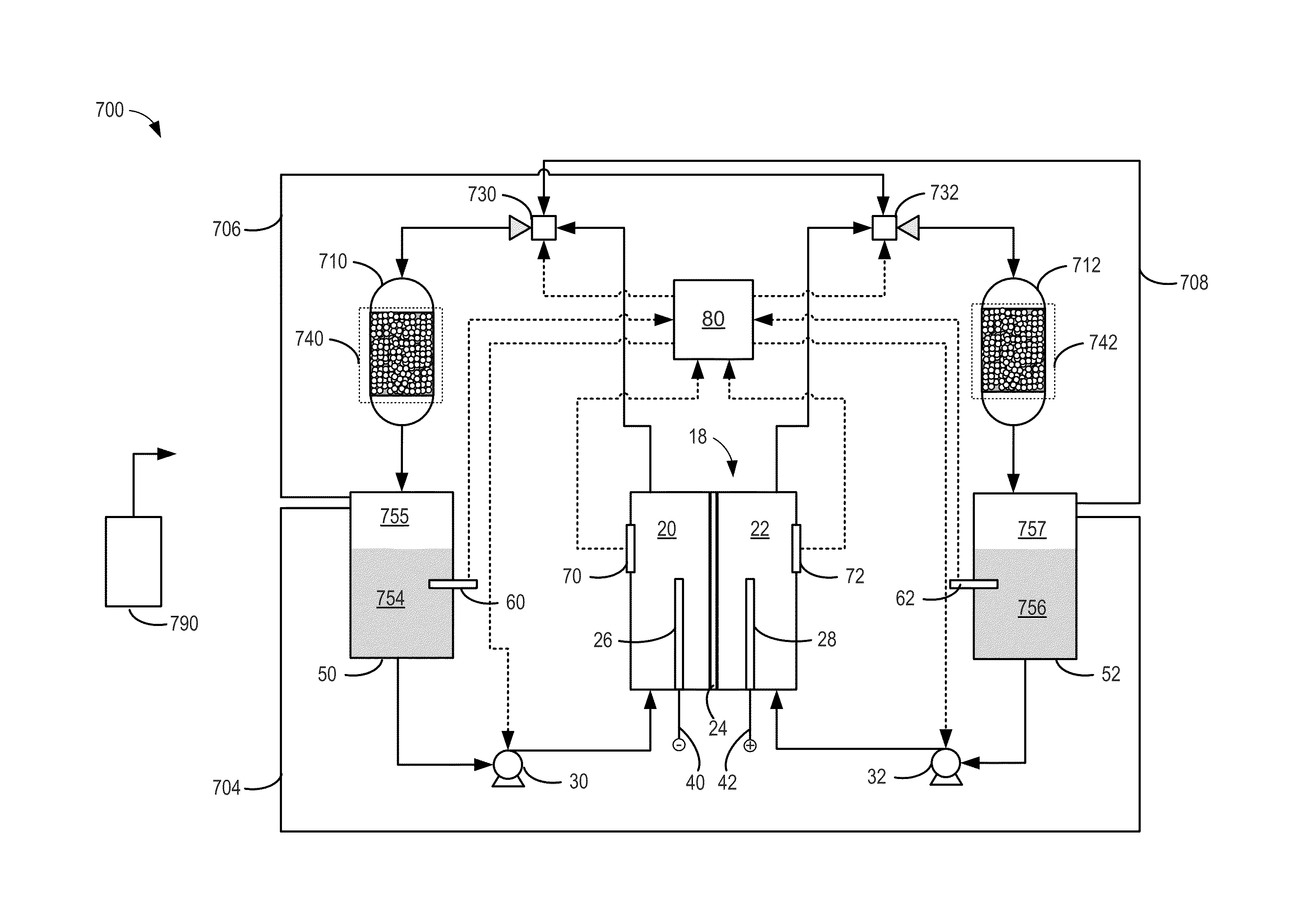
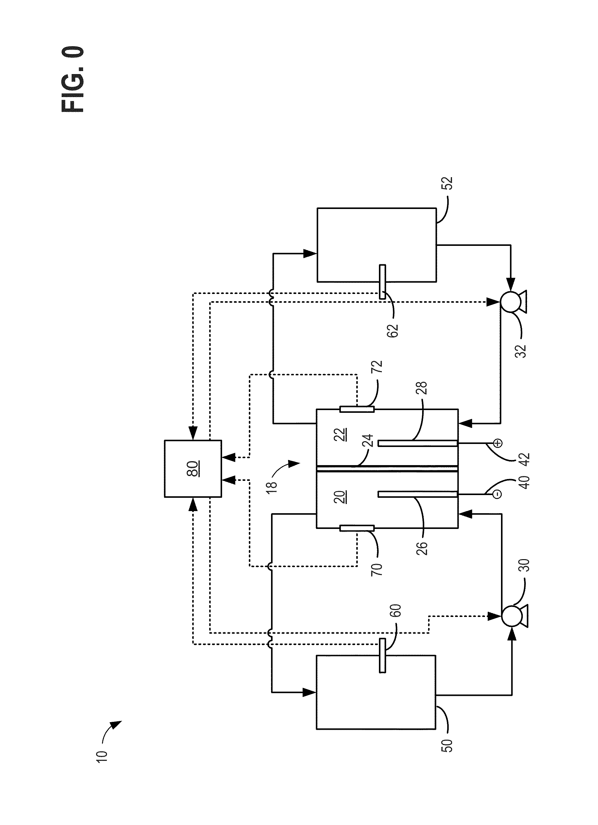
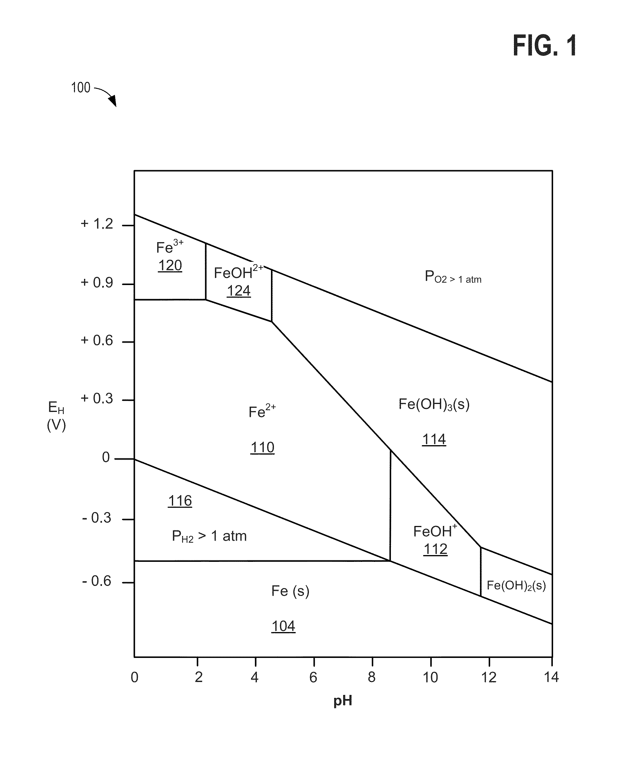
[0018]FIG. 0 illustrates an example schematic for a redox flow battery. FIG. 1 illustrates a Pourbaix diagram for iron, showing the impact of changing electrolyte pH on electrolyte stability. FIG. 2 illustrates an example process for testing a rebalancing reaction for rebalancing electrolytes in a redox flow battery system. FIGS. 3-6 show example graphs of test data used for characterizing the rebalancing reaction for rebalancing electrolytes in a redox flow battery system. FIGS. 7-10 illustrates example embodiments of systems and methods for rebala...


PUM


Abstract

A method of rebalancing electrolytes in a redox flow battery system comprises directing hydrogen gas generated on the negative side of the redox flow battery system to a catalyst surface, and fluidly contacting the hydrogen gas with an electrolyte comprising a metal ion at the catalyst surface, wherein the metal ion is chemically reduced by the hydrogen gas at the catalyst surface, and a state of charge of the electrolyte and pH of the electrolyte remain substantially balanced.

Description

CROSS REFERENCE TO RELATED APPLICATION[0001]This application claims priority to U.S. Provisional Patent Application Ser. No. 61 / 832,671, filed Jun. 7, 2013 and entitled METHOD AND SYSTEM FOR REBALANCING ELECTROLYTES IN A REDOX FLOW BATTERY SYSTEM, the entire disclosure of which is herein incorporated by reference.BACKGROUND AND SUMMARY[0002]Redox flow batteries store electrical energy in a chemical form and subsequently dispense the stored energy in an electrical form via a spontaneous reverse redox reaction. Conversion between the chemical and electrical energy occurs in a reactor cell. One issue with conventional redox flow batteries is that over time the electrolyte state of charge can become imbalanced, thereby decreasing battery capacity due to hydrogen generation from the electrolyte via side reactions. For example, hydrogen gas is emitted as an electrochemical byproduct during battery charging. As another example, in a hybrid redox flow battery, hydrogen gas is emitted as a b...

Claims


Application Information

Patent Timeline
11 Dec 2014
Publication
US20140363747A1
IPC
H01M8/06; H01M8/20; H01M8/18
CPC
H01M8/0693; H01M8/20; H01M8/188; Y02E60/50
Inventors
EVANS, CRAIG E.; SONG, YANG