Liquid developer containing electro-conductive particles and an electro-conductive pattern forming method using said material and an electro-conductive pattern forming apparatus using said material

a technology of liquid developer and electro-conductive particles, which is applied in the direction of developers, electrographic process equipment, instruments, etc., can solve the problems of not being able to produce variable patterns within a single set of screens, not being able to meet the requirements of high production volume, and not being able to produce variable patterns within a single set of plates

Inactive Publication Date: 2014-12-11
AFIT CORP
View PDF1 Cites 5 Cited by
  • Summary
  • Abstract
  • Description
  • Claims
  • Application Information

AI Technical Summary

Problems solved by technology

This is a rudimentary process which is inexpensive, but is not suitable for high production volumes.
Since the screen pattern is fixed, is not capable of producing variable patterns within a single set of screens.
This method is capable of high-quality and high-speed patterning, but is not capable of producing variable patterns within a single set of plates.
Inkjet printing is capable of high-quality printing, but is normally limited to a print swath of less than one inch.
And further, print defects inherent in the technology normally requires an overlapping print mode (“shingling”) for full quality printing.
Thus, a swathing print technology such as inkjet is inherently slow unless many expensive printheads are ganged together to improve printing speeds.
Inkjet printers also require low viscosity fluids for proper jetting, resulting in inks with high levels of solvent is which must be removed after patterning.
This results in a further decrease in net throughput.
The polymers normally interfere with the ability to form electrical conductors or components.
This sintering temperature is incompatible with substrates used for printed circuit applications.
The method of '030 also relies on a plating process (electrolytic or non-electrolytic) to improve the electrical conductivity, is giving rise to environmental issues normally associated with traditional plating processes.
Additionally, a large amount of binder resin is used in order to improve the ability to control the charge, fixing, and dispersion, thereby reducing the opportunity for high conductivity.
However, achieving high conductivity with EP technology has yet to be achieved.
Other issues not taught in these references, but required for an EP technology capable of reliably forming electro-conductive circuits, is to provide high adhesion to a substrate and with little to no background fogging.

Method used


Image

  • Liquid developer containing electro-conductive particles and an electro-conductive pattern forming method using said material and an electro-conductive pattern forming apparatus using said material
  • Liquid developer containing electro-conductive particles and an electro-conductive pattern forming method using said material and an electro-conductive pattern forming apparatus using said material
  • Liquid developer containing electro-conductive particles and an electro-conductive pattern forming method using said material and an electro-conductive pattern forming apparatus using said material

Examples


operational example 1

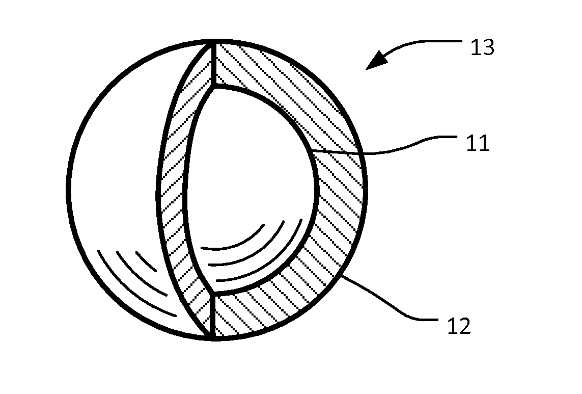
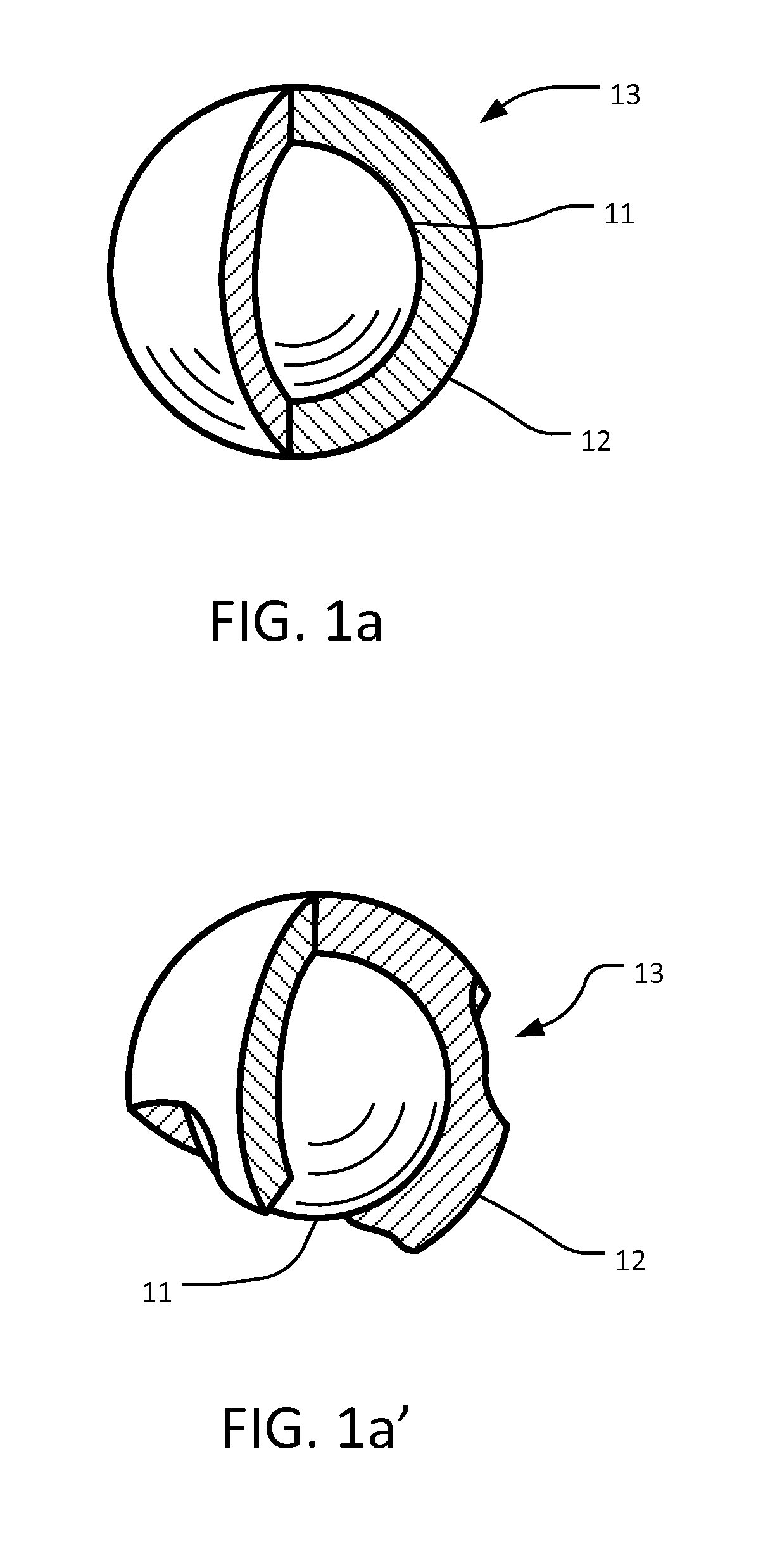
[0058]Cu—Ag 13 particles were prepared with following method: 4 g of copper (II) sulfate pentahydrate was dissolved in 400 g of purified water, then 4 g of ammonia water was added while stirring. Additionally, 8 g of ethylenediaminetetraacetate tetrasodium salt (EDTA 4Na) was added while stirring. Separately, 0.1 g of bipyridyl was dissolved in 8 g of ethyl alcohol, then it was added to the above copper sulfate solution to prepare the plating solution. 200 g of silver particle S211A (manufactured by Daiken chemical Co., Ltd., average particles diameter 1 μm) was added to the plating solution and dispersed for 2 minutes with 9500 rpm spin on the homogenizer. Then 4 g of formalin was added slowly while stirring at 100 rpm, heated at 40° C.˜50° C. and continued stirring for 30 minutes. After this process, it was rinsed 3 times with purified water, then dried for 2 hours at 80° C., resulting in Cu—Ag 13 particles.

[0059]A solution for forming a charge control agent 15 was prepared accord...

operational example 2

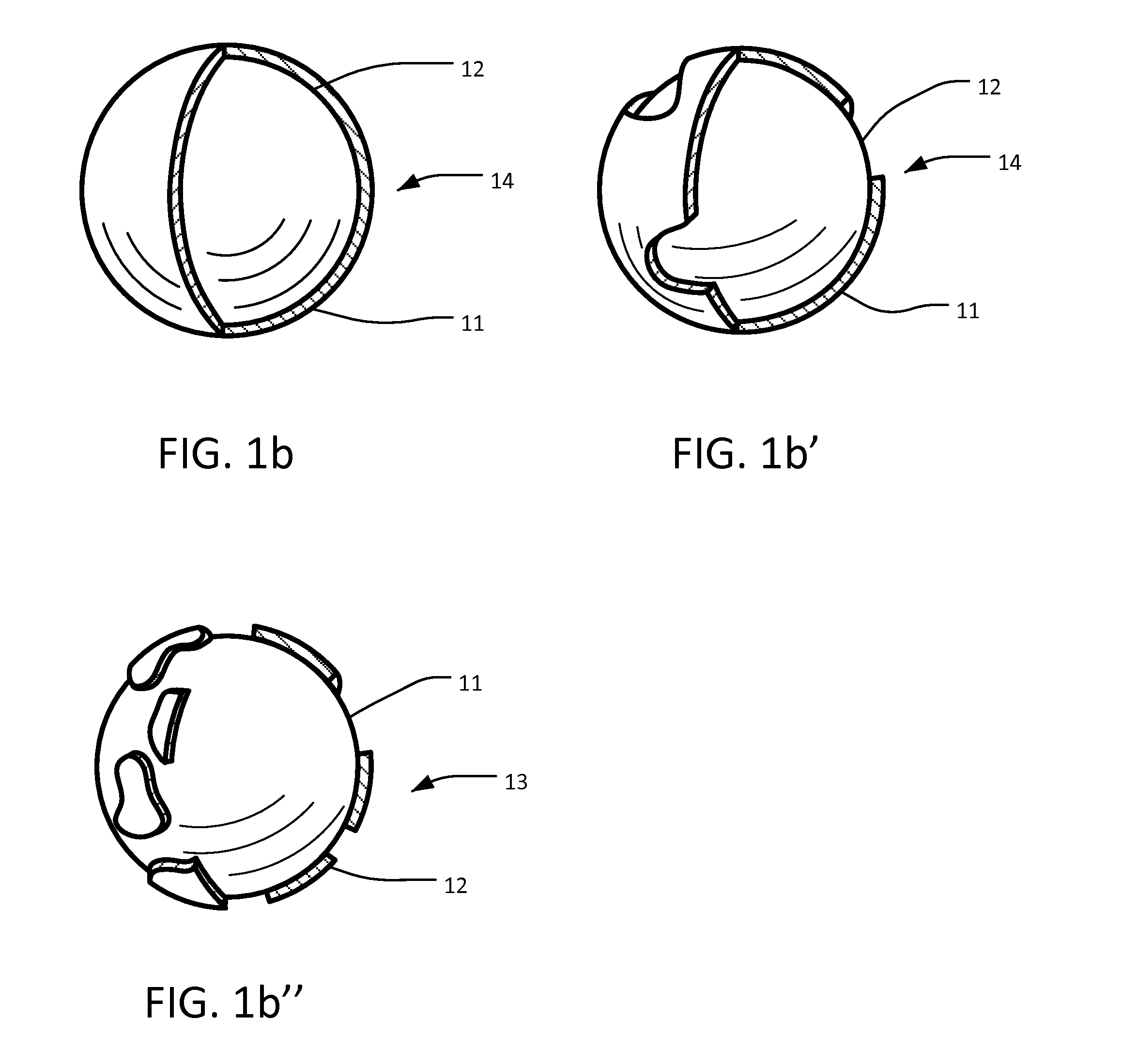
[0065]Silver-plated copper particles can be obtained commercially as well as they can be manufactured through the method such as shown in the Japanese Patent Laid-Open No. 2001-214080 bulletin.

[0066]A solution for forming a charge control agent was prepared according to the following method: 1.0 g of oleic acid was dissolved in 100 g of ethyl alcohol placed in a container.

[0067]Conductive toner particles 16 were formed by providing 200 g of the aforementioned Ag—Cu 14 particles, in addition to 5 mm glass beads, to a container of the aforementioned solution. It was rotated for 4 hours on a ball mill rotation platform at 100 rpm speed. The glass beads were then separated out, and the remaining coated particles were dried at 80° C. for 1 hour in a dryer, resulting in conductive toner particles 16.

[0068]The liquid developer 47 was prepared for Example 2 by providing 0.56 g of Luviskol VA64P (vinyl acetate-vinyl pyrrolidone copolymerized resin, made by BASF), dissolving it in a mixed sol...

operation example 13

[0072]Charge control agent 15 was changed to “G: WP-660” as follows. All other variables were the same as Operational Example 1.

[0073]7.5 g of Ganex WP-660 (alkylated polyvinylpyrrolidone, made by ISP Japan) was added to 50 g of Isopar L (made by ExxonMobil) and heated to 80° C. to dissolve and let it cooled down to the room temperature. This solution was slightly milky. 100 g of copper plated silver (Cu—Ag 13) particles prepared by the same method as Operation Example 1 were added to the solution and additionally 250 g of alumina balls of 5 mm diameter were added. They were placed and sealed in a container and rotated at a rate of 90 rpm for 2 hours on a ball mill rotation platform. When it was finished, the whole content was taken out and the alumina balls were separated. The liquid developer was prepared after 160 g of Isopar L was added.


PUM


Abstract

A novel liquid toner development system is disclosed. The liquid development system includes conductive core-shell particles comprising silver-copper or copper-silver. A novel apparatus and method relying on the novel liquid toner development system results in electro-conductive patterning capable of high conductivity with low background fogging, reduced processing time and reduced environmental impact.

Description

CROSS-REFERENCE TO RELATED APPLICATIONS[0001]This application claims priority under 35 USC §119 to Japanese Patent Application No. 2013-122583 filed on Jun. 6, 2013, now Japanese Patent Registration No. 5,336,680 registered on Aug. 9, 2013, the contents of which are hereby incorporated by reference.BACKGROUND[0002]1. Field of the Invention[0003]The present invention is directed to electro-conductive deposition methods. More particularly, the invention is directed to a liquid toner development system, and pattern forming method and apparatus capable of electro-conductive deposition.[0004]2. Description of Related Art[0005]Electro-conductive patterning is generally within the field of “printed electronics”, in which electrical conductors, or passive or active electrical components are formed on a substrate. Printed electronics is normally an additive process, wherein material is deposited on a substrate to form a predefined pattern. Multiple layers may be deposited of the same materia...

Claims


Application Information

Patent Timeline
Patent Type & Authority Applications(United States)
IPC IPC(8): G03G9/00
CPCG03G15/10G03G9/12G03G9/135
Inventor YOSHIDA, ICHIROIINO, SHUJI
Owner AFIT CORP
Why Eureka
Try Eureka