
Spring force assembly for biasing or actuating stoppers of syringes, injection pen cartridges and the like

Active Publication Date: 2014-12-11
ROCHE DIABETES CARE INC
View PDF4 Cites 41 Cited by
  • Summary
  • Abstract
  • Description
  • Claims
  • Application Information

AI Technical Summary

Benefits of technology

The technical effect of this patent is the provision of a spring force assembly for biasing a displaceable stopper of a liquid medicament cartridge or a syringe. This assembly includes a spring element, two brace elements and two coupling elements which are operationally coupled to each other in such a way that they restrict the distance between the brace elements to a certain maximum value, which also restricts the possible expansion of the spring element. This results in a more stable and reliable biasing of the displaceable stopper of the liquid container or syringe.

Problems solved by technology

While several designs for such dosing units are known in the art, they are rather complex, expensive and critical with respect to large scale manufacture.
However, the force resulting from the achievable pressure differential over the displaceable stopper will typically be too small to overcome the sticking friction force between stopper and cartridge wall.
However, since the fluidic suction pressure that can be exerted by a dosing unit cannot exceed atmospheric pressure, some spring biasing is typically required also for such a design.
At the same time the pressure differential should not be too large, since this could be detrimental in view of upstream leakage.
Thus such springs are prone to getting caught, particularly when they are applied in reusable units, and thus have to be recompressed when an emptied cartridge is replaced.
Incorrectly recompressed springs may become damaged, or may fail, thereby potentially causing dosing errors caused by incomplete refilling of the dosing unit, or by aspiration of gas bubbles resulting from underpressure in the cartridge.
In addition, such recompression can be a difficult manual task, particularly when long springs are used, or for patients that have impaired fine motor skills
The mounting of a long compression spring into an infusion pump device is complicated and difficult to automatize, which increases the manufacturing costs.

Method used


Image

  • Spring force assembly for biasing or actuating stoppers of syringes, injection pen cartridges and the like
  • Spring force assembly for biasing or actuating stoppers of syringes, injection pen cartridges and the like
  • Spring force assembly for biasing or actuating stoppers of syringes, injection pen cartridges and the like

Examples


Embodiment Construction

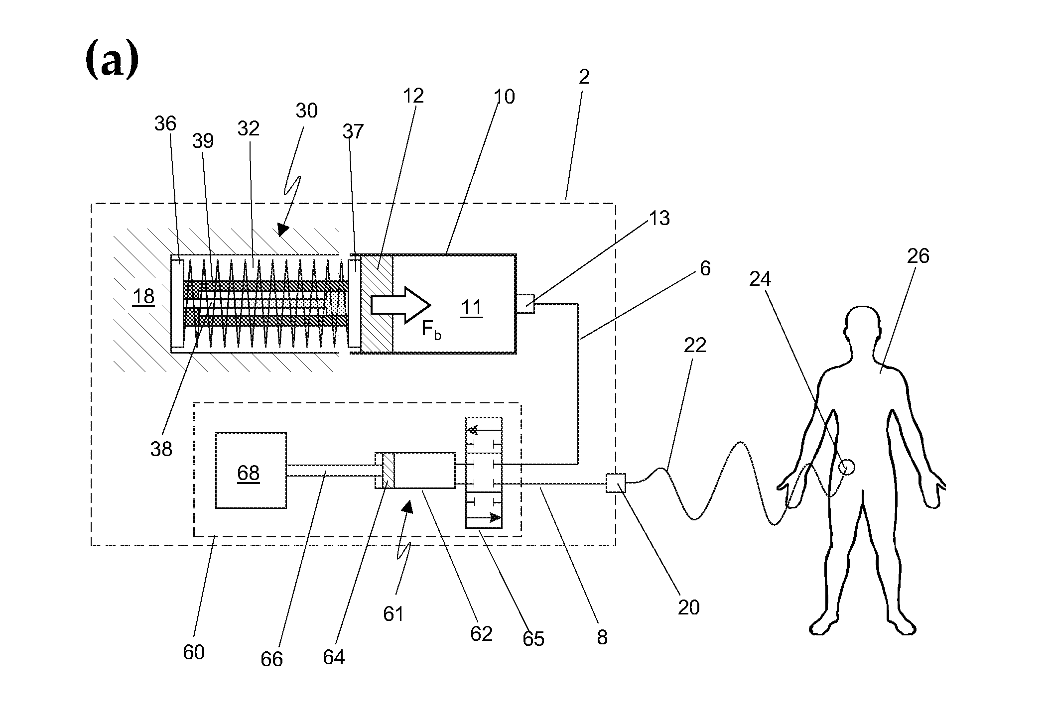
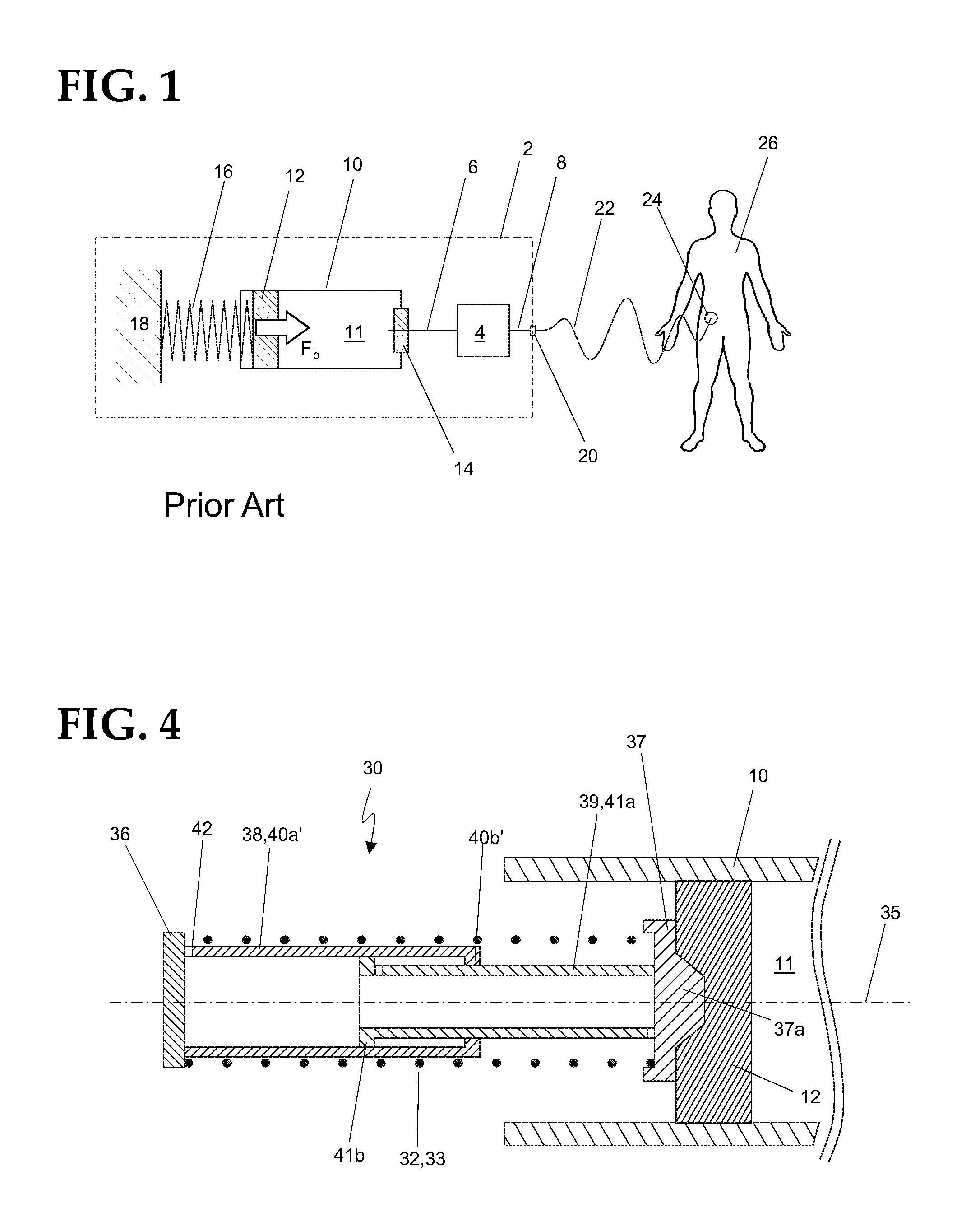
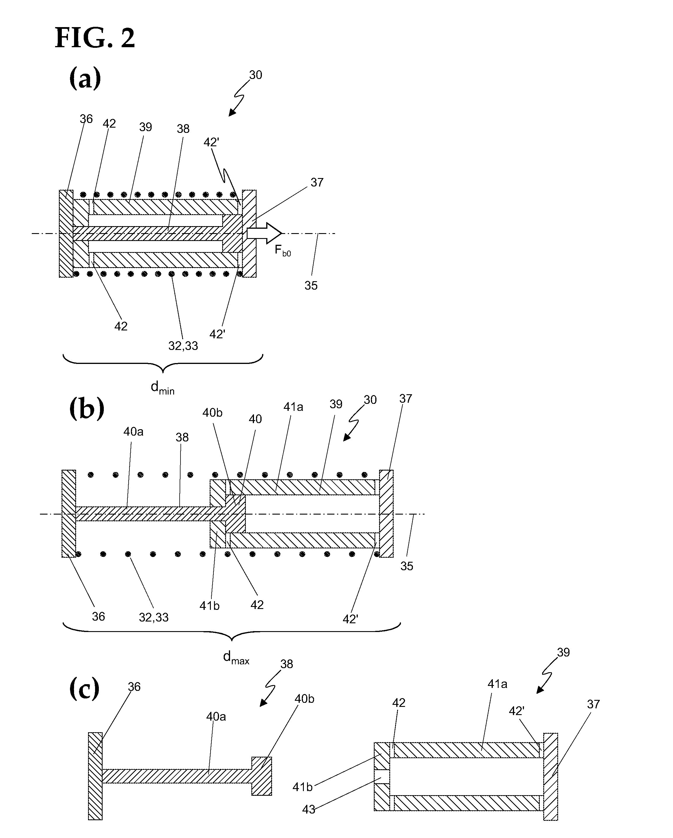
[0036]A first embodiment of a spring force assembly 30 according to the disclosure is schematically shown in FIG. 2. The assembly is intended to be mounted in an infusion pump device and to be operationally coupled to a liquid medicament cartridge.

[0037]Two brace elements 36, 37 are arranged on the longitudinal ends of a spring element 32 in the form of a helical compression spring 33. The brace elements are designed in such a way that they can support the spring element 32 arranged between them. In the shown embodiment the brace elements are realized as disks with a diameter that is larger than the outer diameter of the helical spring.

[0038]The assembly has two coupling elements interacting in the form of a telescope, arranged inside the spring element. A first coupling element 38 comprises a shaft 40a, which is attached on one end to a first 36 of said brace elements, and on the other end to a disk 40b. A second coupling element 39 comprises a tube element 41a, which is attached o...


PUM


Abstract

A spring force assembly for biasing a displaceable stopper of a liquid medicament cartridge including a spring element arranged along a longitudinal axis, with brace elements and coupling elements, with the coupling elements restricting the distance between the brace elements which also restricts the possible expansion of the spring element.

Description

CROSS-REFERENCE TO RELATED APPLICATIONS[0001]The present application is a continuation of International Application No. PCT / EP2012 / 053293, filed Feb. 27, 2012, which is hereby incorporated by reference in its entirety.FIELD OF TECHNOLOGY[0002]This application relates to spring force assemblies for biasing or actuating stoppers of syringes, injection pen cartridges and the like, infusion pump devices with spring force units for biasing or actuating stoppers, and the methods of use of such spring force assemblies.BACKGROUND[0003]Insulin infusion pumps and insulin injection pens are useful devices in the treatment of diabetes mellitus, since they allow controlled parenteral administration of highly potent insulin solution by the patient himself, in variable but exactly measured doses, as required by the momentary physiological need of a patient. Similar devices are also useful for the treatment of other medical conditions, such as e.g. pain treatment.[0004]Common insulin pump devices a...

Claims


Application Information

Patent Timeline
IPC IPC(8): A61M5/145A61M5/20
CPCA61M5/1454A61M2005/14506A61M5/2033A61M5/24A61M5/31565A61M5/31576A61M5/3159
Inventor NIKLAUS, HANSPETERSCHAAD, FLORIANTEUTSCH, DAVID
Owner ROCHE DIABETES CARE INC
Learn More