
Methods and apparati for handling, heating and cooling a substrate upon which a pattern is made by a tool in heat flowable material coating, including substrate transport, tool laydown, tool tensioning and tool retraction

a technology of heat flowable material and method, which is applied in the direction of manufacturing tools, instruments, photomechanical devices, etc., can solve the problems of separating the tool from the substrate, damage, and air pollution, and achieve the effect of preventing or at least minimizing air pollution

Active Publication Date: 2014-12-18
CUBICPV INC
View PDF9 Cites 13 Cited by
  • Summary
  • Abstract
  • Description
  • Claims
  • Application Information

AI Technical Summary

Benefits of technology

The patent text describes a system and method for creating patterned elements on a substrate quickly and without damaging the substrate. The system should be able to heat and cool the substrate and the flowable material quickly, without causing stresses in the wafer that might cause it to fracture. The system should also be able to securely and rapidly move the substrate to a processing station, hold it in place, and then securely and rapidly move it to a subsequent processing station. It should also be able to rapidly remove the tool from the resist material after patterning without damaging the substrate or the pattern. The system should also be reliable and reproducible. The technical effects of this invention include faster and more efficient patterning, reduced risk of damage to the substrate and pattern, and improved reliability and reproducibility of the patterning process.

Problems solved by technology

Such damage may arise if too much force were to be applied to the substrate while pressing the pattern.
Damage may also arise due to thermal cycling that is applied to soften the flowable material for patterning, and then to again harden it for retaining such patterns.
Such damage might also arise from separating the tool from the substrate, as covered with the flowable material.
Other potential problems may arise if air becomes trapped between the tool and the resist coated wafer.
Trapped air gives rise to unwanted pressure regimes, that are hard to anticipate and to control because such trapped air may also give rise to locations of spuriously non-uniform pressure, and thus, irregularity in the size of the holes in the resist created.
Another problem that may arise is because the tool is heated and cooled during the process.
This could give rise to dimensional changes, which would then give rise to unwanted dimensional differences in the pattern made in the resist material.

Method used


Image

  • Methods and apparati for handling, heating and cooling a substrate upon which a pattern is made by a tool in heat flowable material coating, including substrate transport, tool laydown, tool tensioning and tool retraction
  • Methods and apparati for handling, heating and cooling a substrate upon which a pattern is made by a tool in heat flowable material coating, including substrate transport, tool laydown, tool tensioning and tool retraction
  • Methods and apparati for handling, heating and cooling a substrate upon which a pattern is made by a tool in heat flowable material coating, including substrate transport, tool laydown, tool tensioning and tool retraction

Examples


Embodiment Construction

Overview

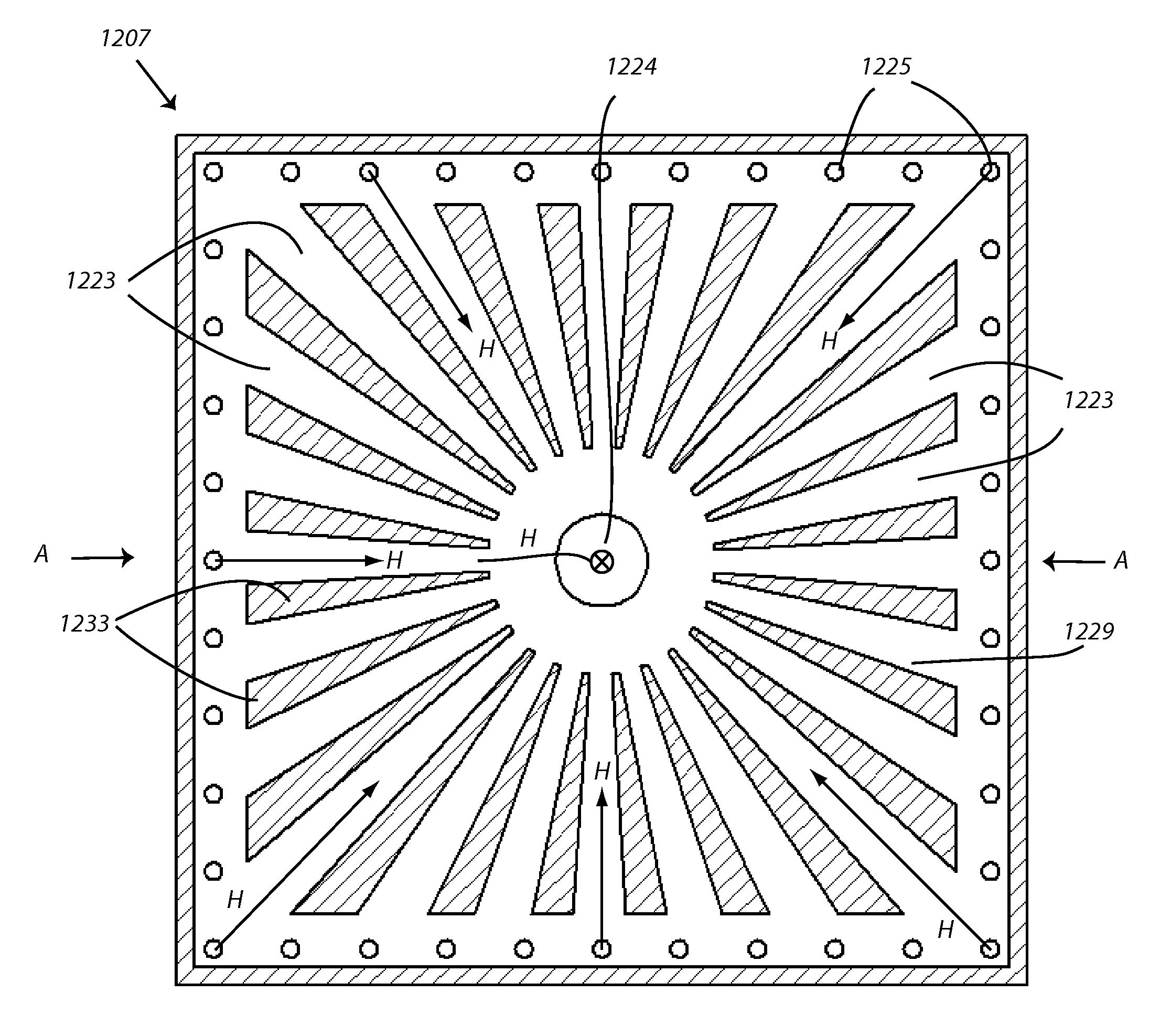
[0047]FIGS. 7A-7H show, schematically, a cross section view of an apparatus for wedging and illustrates a representative process sequence. A chuck 707 heats and cools a resist-coated substrate wafer 701. (Internal flow channels for heating and cooling chuck are not shown in FIGS. 7A-7F, but are shown in FIGS. 9, 9A, 10 and 10A). A porous belt 703 transports the resist-coated wafer 701 onto and off of the chuck. The chuck 707 is supported by thermally insulating support 710. As shown in FIG. 7, a vacuum is pulled through vacuum channel 708, vacuum plenum 709 and vacuum channels 711 in the chuck and through the porous belt 703, to hold the wafer down against the belt and chuck at a workpiece station. The workpiece is in place at the station in FIGS. 7 and following. This vacuum hold down provides for good thermal contact between the wafer and the chuck and later, will aid in peeling the tool from the wafer. The flexible tool / stamp 706 is clamped in a ring 712 under pre-tension...


PUM

PropertyMeasurementUnit
Lengthaaaaaaaaaa
Lengthaaaaaaaaaa
Lengthaaaaaaaaaa

Abstract

A workpiece is transported using a porous belt, which belt delivers a workpiece to a chuck, upon which the workpiece is held by vacuum. The belt can be porous PTFE. A flexible stamp is preheated, before it is applied to a workpiece, by drawing the stamp toward a heated plate, for instance by vacuum.

Description

RELATED DOCUMENTS[0001]The benefit of U.S. Provisional Application No. 61 / 538,542, filed Sep. 23, 2011, entitled METHODS AND APPARATI FOR HANDLING, HEATING AND COOLING A SUBSTRATE UPON WHICH A PATTERN IS MADE BY A TOOL IN HEAT FLOWABLE MATERIAL COATING, INCLUDING SUBSTRATE TRANSPORT, TOOL LAYDOWN, TOOL TENSIONING, AND TOOL RETRACTION, is hereby claimed, and the entire disclosure of which is hereby incorporated fully herein, by reference.[0002]A PCT application, designating the United States, is being filed on the same date, herewith, in the name of Emanuel M. Sachs, submitted by the USPTO Electronic Filing System under Attorney Docket No. 1366-0066-0070PCT, entitled, TECHNIQUES FOR IMPROVED IMPRINTING OF SOFT MATERIAL ON SUBSTRATE USING STAMP INCLUDING UNDERFILLING TO LEAVE A GAP AND PULSING STAMP, which PCT application claims priority to US Provisional Application No. 61 / 538,489 of the same title, filed on Sep. 23, 2011. The PCT application is referred to herein below as the co-pen...

Claims


Application Information

Patent Timeline
IPC IPC(8): B29B13/02
CPCB29B13/02B29C59/02B29C2059/023G03F7/0002
Inventor SACHS, EMANUEL M.KANE, PETER E.GATES, HOLLY G.HARRIS, DAMIAN W.POLITO, BENJAMIN F.INIRIO, HECTOR A.
Owner CUBICPV INC
Learn More