Mixing rotor and internal mixer
- Summary
- Abstract
- Description
- Claims
- Application Information
AI Technical Summary
Benefits of technology
Problems solved by technology
Method used
Image

Examples
first embodiment
[0028](Mixing Rotor of First Embodiment)
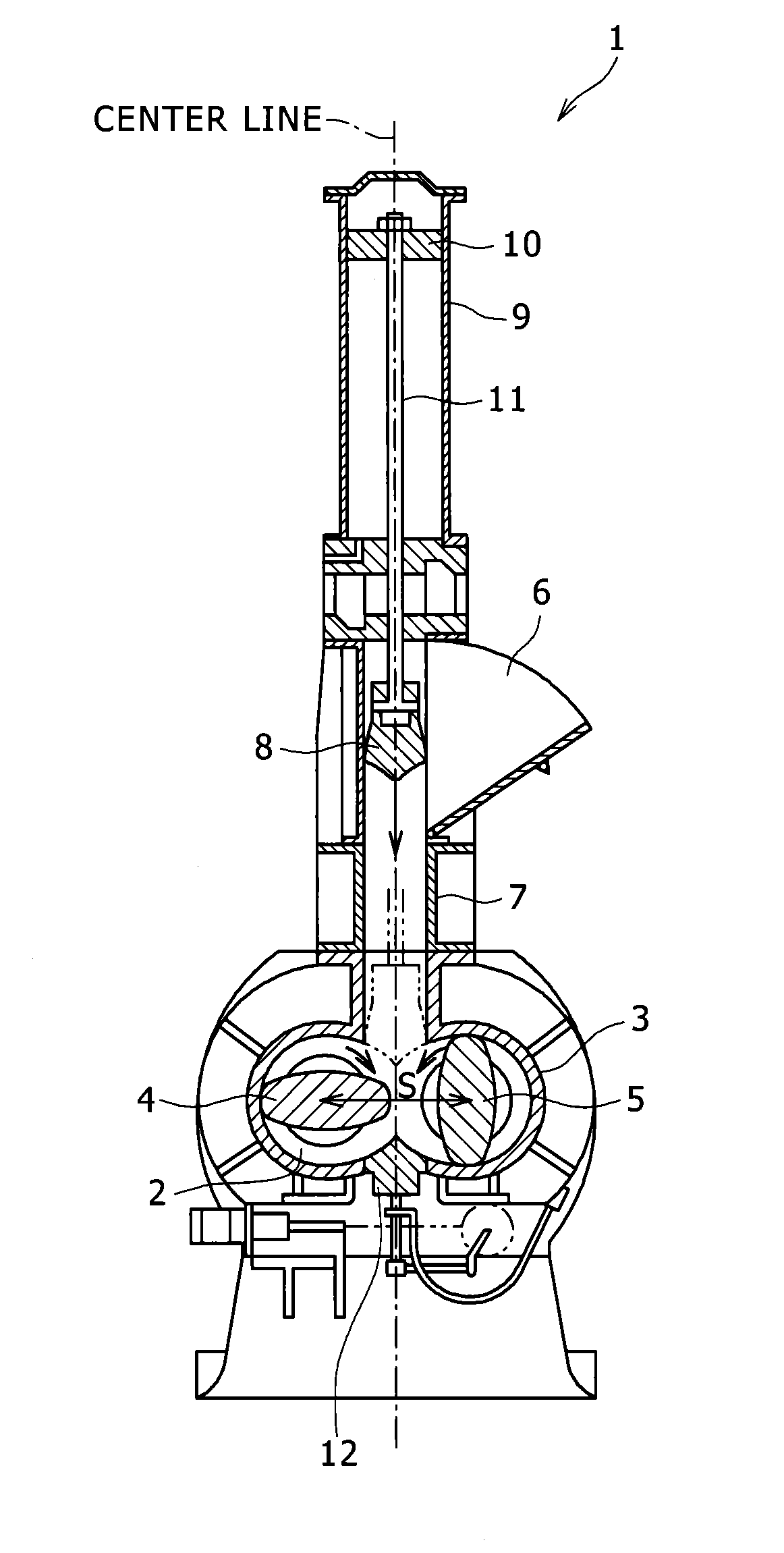
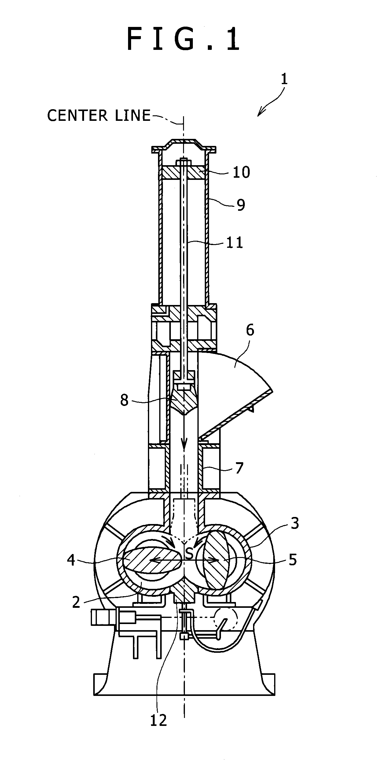
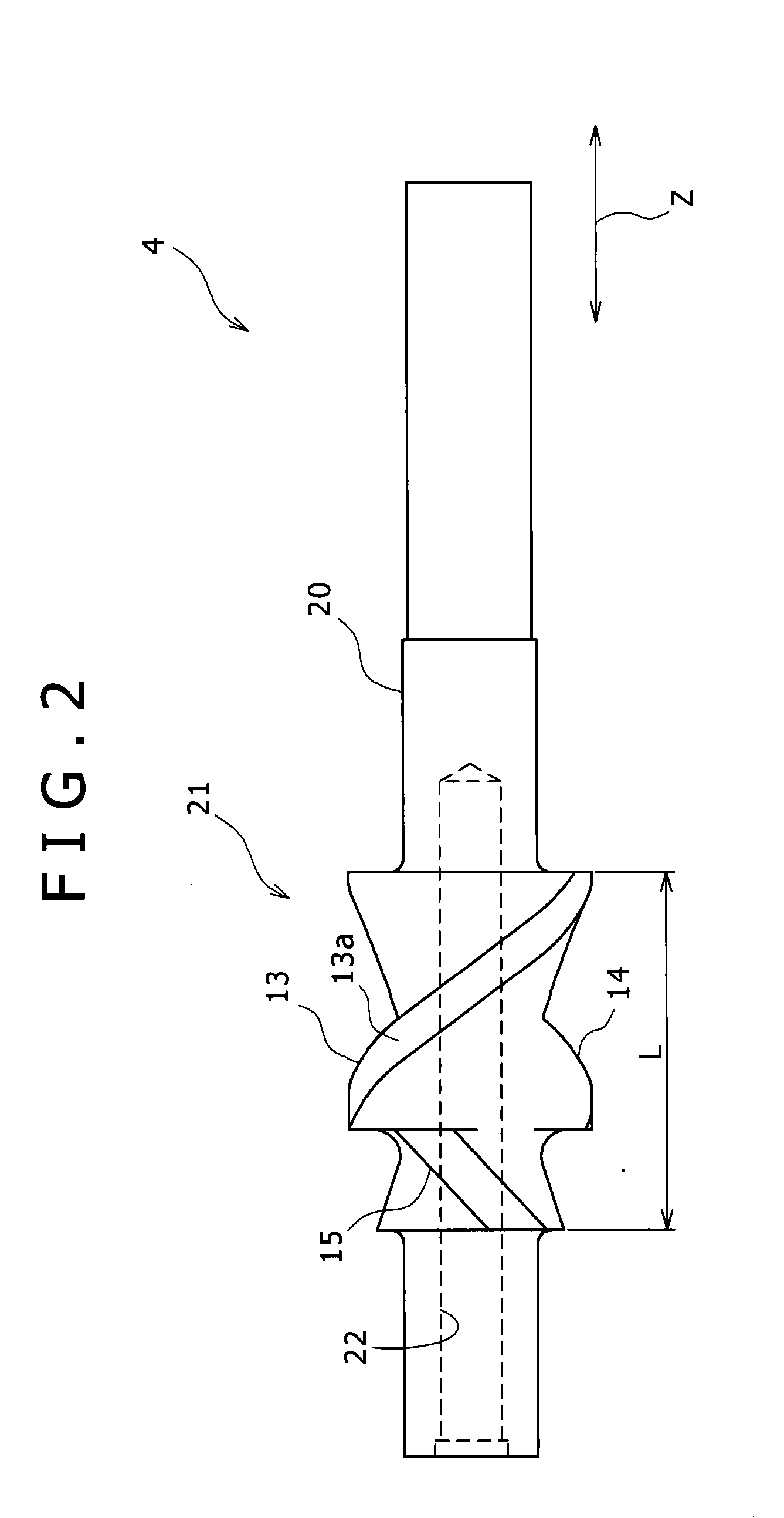
[0029]Referring to FIGS. 1 to 4, the mixing rotors 4 and 5 according to a first embodiment of the present invention will be described. FIG. 2 is a top view for illustrating the mixing rotor 4.
[0030]Each of the mixing rotors 4 and 5 includes a rotor shaft portion 20 that includes a cooling passageway 22 formed therein and a mixing blade portion 21 that is formed in an outer circumferential portion of the rotor shaft portion 20. The mixing blade portion 21 of each of the mixing rotors 4 and 5 has a predetermined length L in an axis direction Z (hereinafter, “rotor axis direction Z”) of the mixing rotor 4 or 5. Rotary joints that are used to supply a cooling medium to the cooling passageways 22 formed in the mixing rotors 4 and 5 and to discharge the cooling medium from the cooling passageway 22 are connected to the mixing rotors 4 and 5, respectively. Each of the cooling passageways 22 is a bottomed hole having a circular cross-section. The cool...
second embodiment
[0062](Mixing Rotor of Second Embodiment)
[0063]Next, a mixing rotor according to a second embodiment of the present invention will be described. The mixing rotor according to the second embodiment differs from the mixing rotor according to the first embodiment in a magnitude of the land center angle (land width W). The mixing rotor according to the second embodiment is configured similarly to that according to the first embodiment in the other configurations. The land center angles of the blades of the mixing rotor according to the second embodiment are all set to 15°.
[0064](Calculation Result of Leakage Amount of Material to be Mixed to Blade Rear Surface)
[0065]The leakage amount of the material to be mixed to the blade rear surface is calculated by changing the land center angle. The calculation result is illustrated in FIG. 5. In the graph of FIG. 5, the vertical axis indicates the leakage amount (%), and this leakage amount is represented by percentage with the leakage amount in...
PUM
| Property | Measurement | Unit |
|---|---|---|
| Angle | aaaaa | aaaaa |
| Angle | aaaaa | aaaaa |
| Angle | aaaaa | aaaaa |
Abstract
Description
Claims
Application Information
 - R&D Engineer
- R&D Manager
- IP Professional
- Industry Leading Data Capabilities
- Powerful AI technology
- Patent DNA Extraction
Browse by: Latest US Patents, China's latest patents, Technical Efficacy Thesaurus, Application Domain, Technology Topic.
© 2024 PatSnap. All rights reserved.Legal|Privacy policy|Modern Slavery Act Transparency Statement|Sitemap