
Candle Dispenser

a dispenser and candle technology, applied in the field of candle dispensers, can solve the problems of not completely addressing pyrolysis and/or uneven healing, less successful dispensing of certain particularly desirable pest control materials, and heat spikes directly ever the flame, etc., and achieves the effect of easy release of active upon heating and low cos

Active Publication Date: 2014-12-18
SC JOHNSON & SON INC
View PDF60 Cites 6 Cited by
  • Summary
  • Abstract
  • Description
  • Claims
  • Application Information

AI Technical Summary

Benefits of technology

The invention is a device that uses a refill to dispense air treatment chemicals from a candle. The refill has a container, wick, and heat transfer structure. The heat transfer structure includes a fin structure and a lower radial extension that can transfer heat to a porous substrate that contains the air treatment chemical. The refill can be used with a separate wax refill and substrate refill, making it more convenient for consumers. The system self-adjusts as the substrate gets closer to being used up, ensuring consistent dispensing. The device is also designed to prevent unintended human contact with the substrate and is relatively inexpensive to produce.

Problems solved by technology

While this is a common technique for dispensing a variety of fragrances, typically it has been less successful when dispensing certain particularly desirable pest control materials.
However, these devices typically placed the pad directly over the candle flame, leading to heat spikes directly ever the flame, as wed as sometimes too little heat adjacent the periphery of the pad.
While this made the pad able to more efficiently dispense some additional types of air treatment chemicals, it did not completely address pyrolysis and / or uneven healing problems.
However, this type of heat transfer was relatively inefficient, and (in any event) placing the active at a typical gripping position for the candle could cause some consumers to have concerns about the possibility of touching and / or interfering with the active.

Method used


Image

  • Candle Dispenser
  • Candle Dispenser
  • Candle Dispenser

Examples


Embodiment Construction

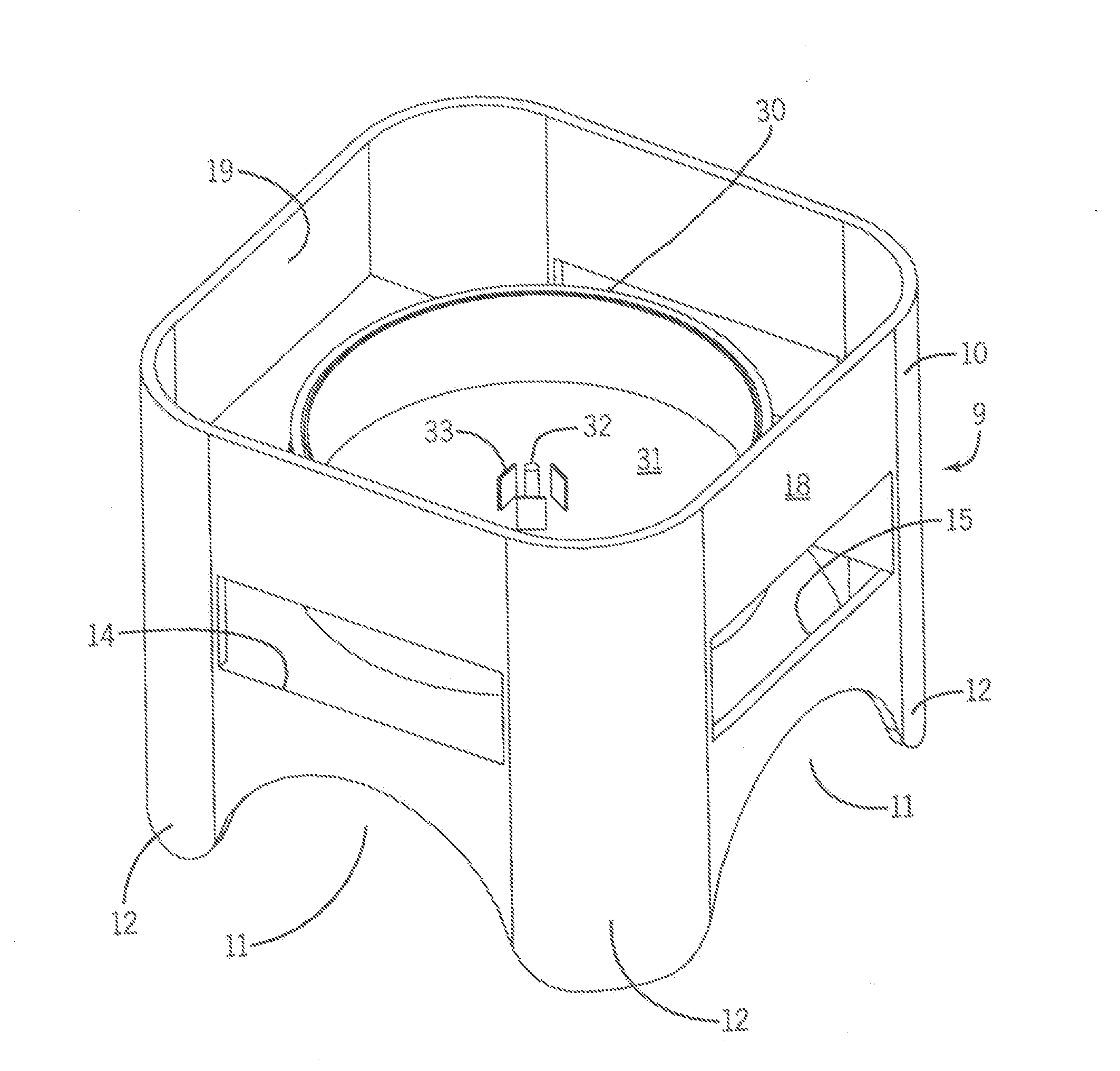
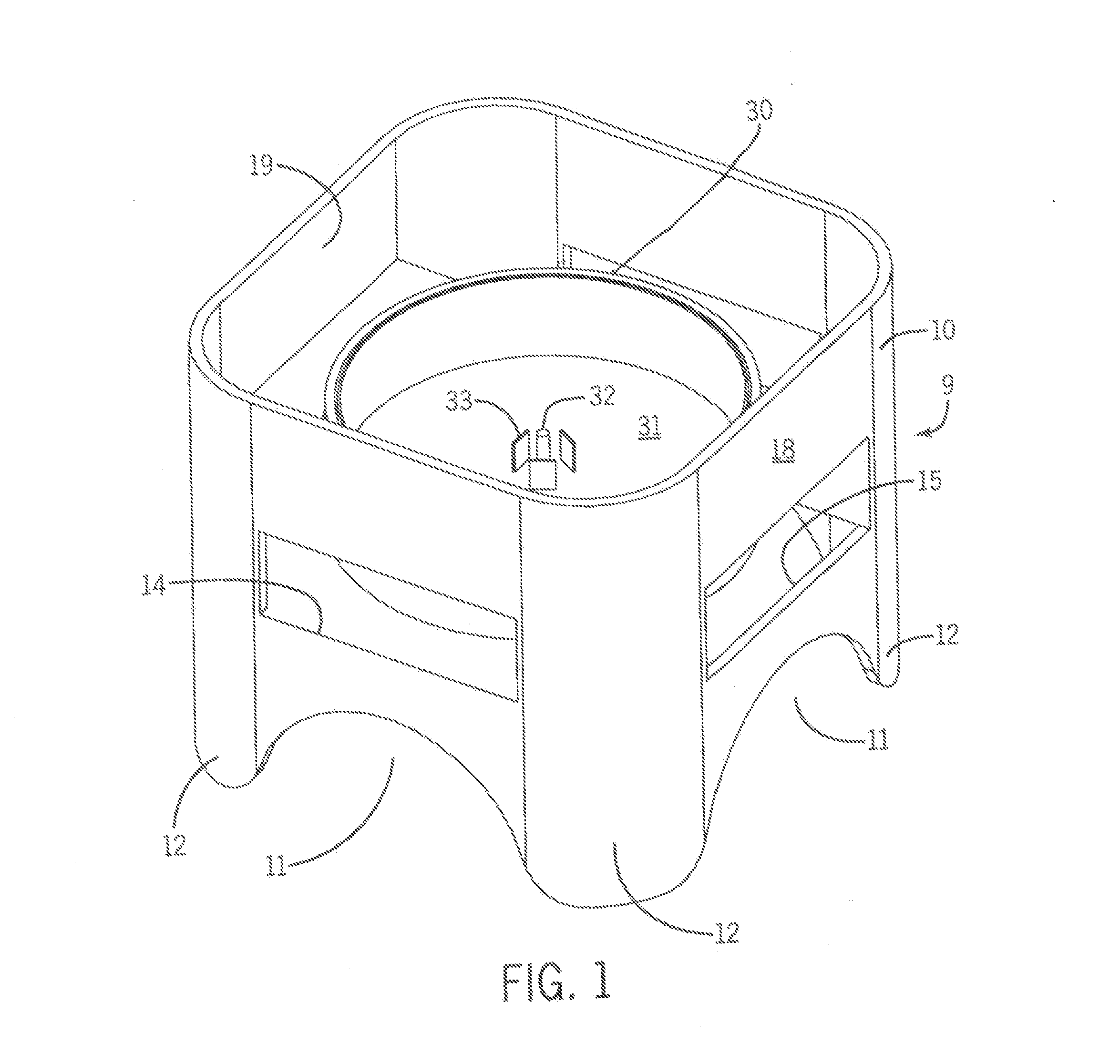
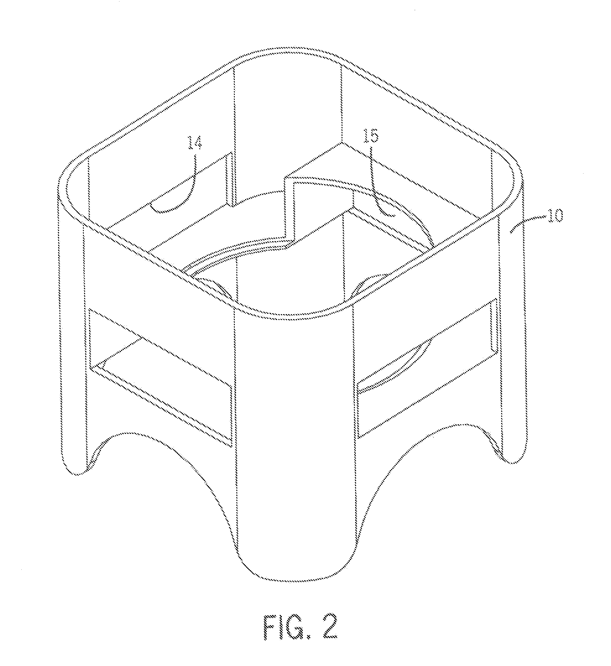
[0034]A first assembly 9 for dispensing an air treatment chemical is shown in FIGS. 1-5. Its major subcomponents are an outer housing 10 (FIG. 2) and a candle / substrate refill 30 (FIG. 4).

[0035]The outer housing 10 is in the form of a four-legged lower table that has arched apertures 11 between corner legs 12. A support / platform 13 extends horizontally adjacent a first set of opposed slit openings 14, and a second set of opposed slit openings 15. The support / platform 13 has a central, circular opening 16. Upper walls 18 define an internal cavity 19 for holding the refill 30.

[0036]Refill 30 is sized so as to fit within the internal cavity 19, with a bottom portion of the refill open to the area defined by the legs 12 under opening 16. Enough space is left in the internal cavity 19 around the refill 30 so that air may easily pass into opposed slit openings 15, up outside the refill 30, and to the area of the candle wick. This helps feed fresh air to the candle, and ultimately helps ca...


PUM


Abstract

Devices dispenser treatment chemicals in response to heat generated by a candle. Heat transfer elements carry flame heat to an impregnated substrate that is positioned mostly or entirely below the candle. The air treatment chemical vapors are kept away from prolonged direct exposure to flame heat, thereby reducing heat degradation of the active. The candle automatically adjusts heat transfer rates to correct for decreasing amounts of active on the substrate as the substrate sears being used up.

Description

CROSS-REFERENCE TO RELATED APPLICATIONS[0001]Not applicableSTATEMENT REGARDING FEDERALLY SPONSORED RESEARCH / DEVELOPMENT[0002]Not applicableBACKGROUND OF THE INVENTION[0003]The present invention relates to devices that dispense air treatment chemicals from a substrate using the heat of a candle to drive the dispensing. More particularly, the invention relates to such devices that have been configured to protect the air treatment chemical from heat degradation (a / k / a “pyrolysis”) during such dispensing.[0004]A variety of devices are known for dispensing volatilizable air treatment chemicals such as pest control materials (e.g., insecticides, insect repellents, or insect growth control regulators), air scents or deodorizers (e.g. masks), allergen control ingredients, disinfectants, sanitizers or other materials. In some of these devices the air treatment chemical is mixed with candle wax and is dispensed during a candle burning process (where the chemical is released primarily from the...

Claims


Application Information

Patent Timeline
IPC IPC(8): C11C5/00F21V35/00
CPCF21V35/00C11C5/002A01M1/2088A61L9/03A61L2209/133C11C5/006
Inventor SHARMA, NITINGILLIGAN, ALLYCE M.
Owner SC JOHNSON & SON INC
Learn More