
Terminal connection device for a power cable

a technology of connection device and power cable, which is applied in the direction of power cable, coupling device connection, cable, etc., can solve the problems of time and effort, and the most difficult operation of re-connecting existing cables to the new termination, so as to facilitate the connection of the device to the connection point, reduce the possibility of making mistakes, and facilitate the effect of easy connection of power cabl

Active Publication Date: 2014-12-18
3M INNOVATIVE PROPERTIES CO
View PDF10 Cites 16 Cited by
  • Summary
  • Abstract
  • Description
  • Claims
  • Application Information

AI Technical Summary

Benefits of technology

The present invention is a terminal connection device that allows for a quick and easy connection between a cut off power cable and a connection point in a confined space. The device has an integrated splice and termination, reducing the possibility of mistakes during installation. It can be easily made in different lengths and types of power cable without adding manufacturing costs. The device includes a power cable, first and second cable connectors, and a tubular sleeve for protection. The device allows for easy connection to the power cable and easy connection to the connection point using the splice and termination portions of the device. The device can be flexible and partially flexible or rigid, depending on the application. The use of a single tubular sleeve or separate tubular sleeves for splice and termination portions of the device depends on the length of the interface cable and the need for insulation.

Problems solved by technology

When an existing cable termination has to be replaced with a new one (due to repair / maintenance or feature upgrading) without the need to replace the existing power cables (i.e., retro-fitting), the most difficult operation is to re-connect the existing cables to the new termination.
Additionally, when a repair is required, the time it takes to reconnect the power cable is a concern in terms of impact on service continuity and penalty costs for energy network management.

Method used


Image

  • Terminal connection device for a power cable
  • Terminal connection device for a power cable
  • Terminal connection device for a power cable

Examples


Embodiment Construction

[0050]Herein below diverse embodiments of the present invention are described and shown in the drawings wherein like elements are provided with the same reference numerals.

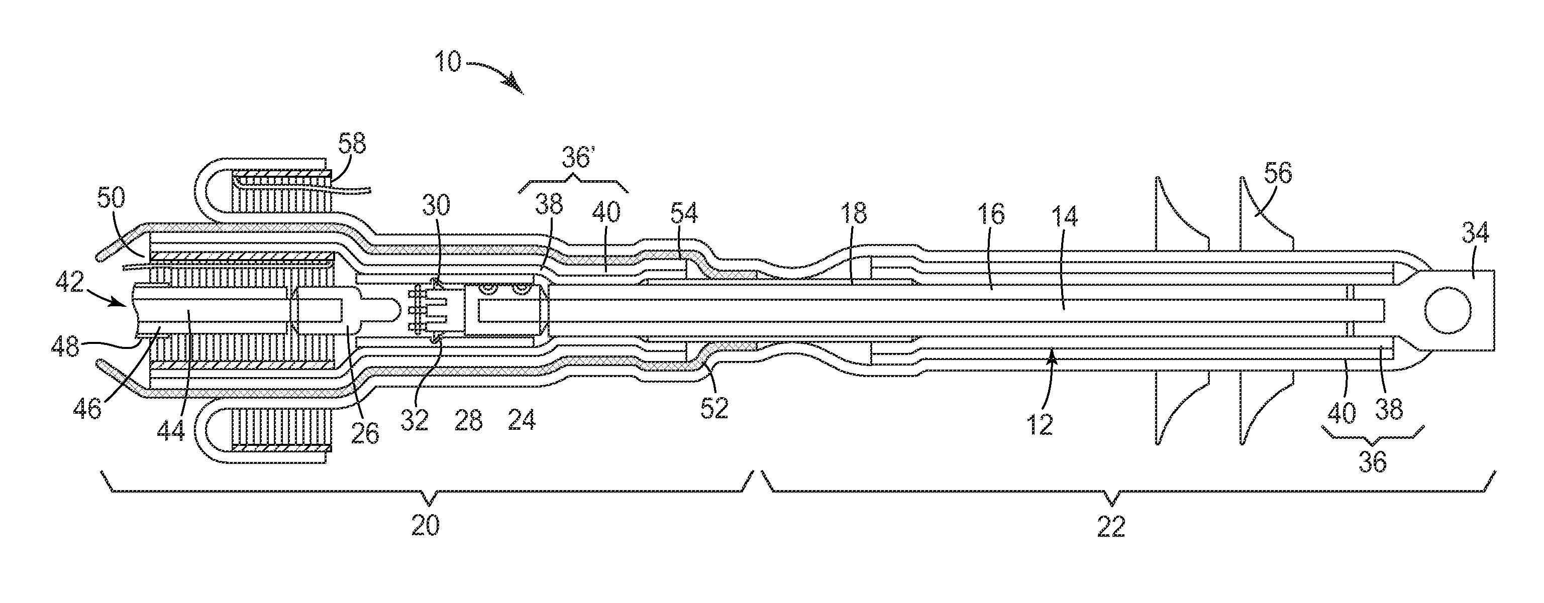
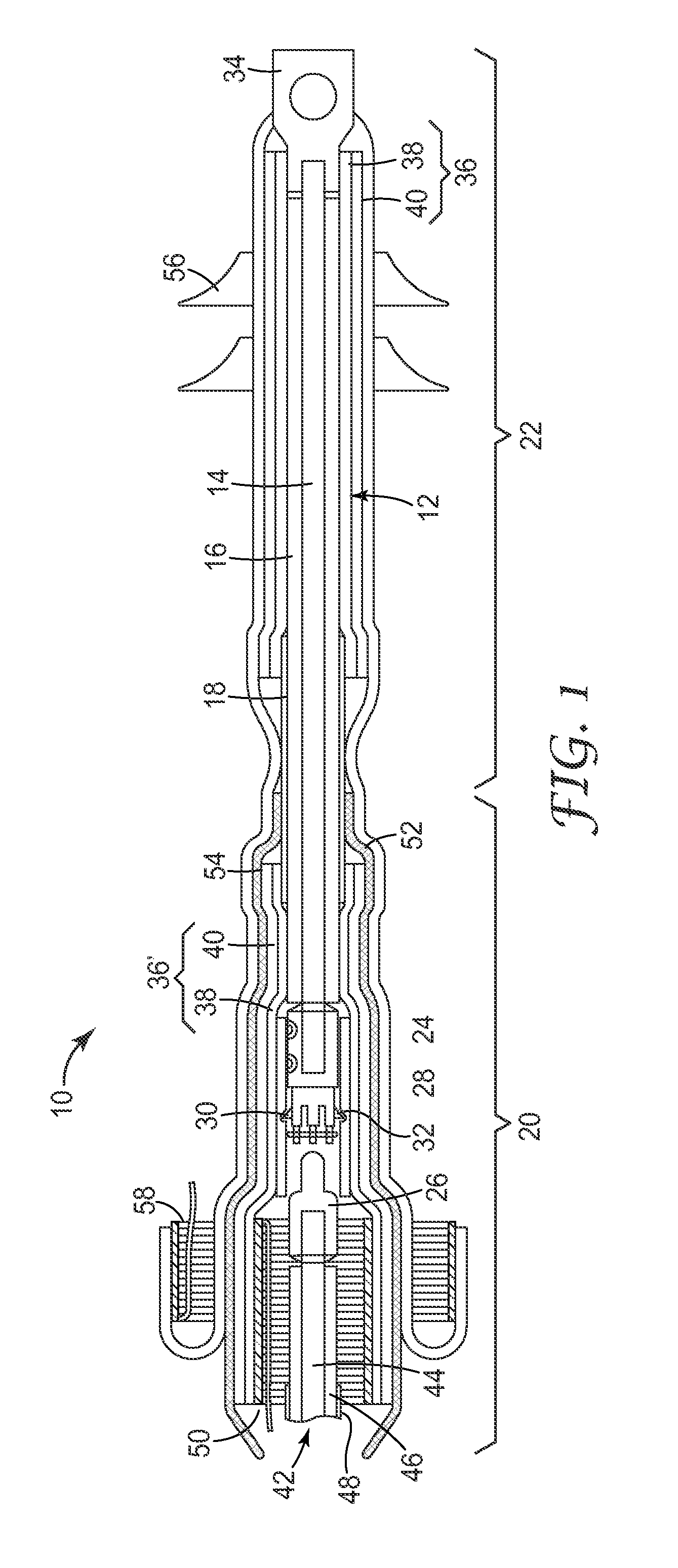
[0051]FIG. 1 shows a first embodiment of a pre-assembled terminal connection device for connecting an end of a medium- or high-voltage power cable to a connection point. The pre-assembled terminal connection device 10 comprises an interface cable 12 having an inner conductor 14, an insulation layer 16 surrounding conductor 14, and a conductive or semiconductor layer (hereinafter referred to as semiconductor layer) 18 surrounding insulation layer 16. As illustrated in FIG. 1, any additional layers of the interface cable 12, such as a metallic cable screen surrounding semiconductor layer 18 and an outer cable jacket surrounding the metallic cable screen are typically removed. However, in some embodiments, these layers may remain on a portion of interface cable 12. Terminal connection device 10 is effectively compris...


PUM

PropertyMeasurementUnit
Digital informationaaaaaaaaaa
Electrical conductoraaaaaaaaaa
Stress optical coefficientaaaaaaaaaa

Abstract

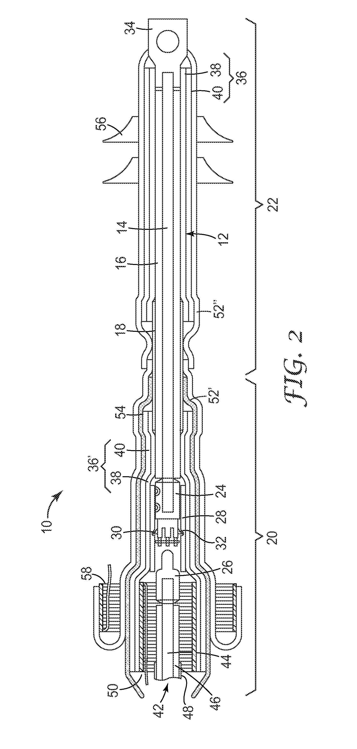
Terminal connection device (10) for connecting an end of a medium- or high-voltage power cable (42) to a connection point, the terminal connection device (10) comprising an interface cable (12) having first and second end portions, comprising an inner conductor (14) and a conductive or semiconductive layer (18). The terminal connection device further comprises a first stress control tube (36) comprising—a stress control element (38), and an insulating layer (40) arranged around the stress control element (38), wherein the first stress control tube (36) is mounted on the first end portion of the interface cable (12). The terminal connection device further comprises a first cable connector (24) for connecting the interface cable (12) to the power cable (42), the first cable connector (24) being connected to the second end portion of the interface cable (12); The terminal connection device (10) further comprises a second stress control tube (36′) comprising a stress control element (38), and an insulating layer (40) arranged around the stress control element (38), wherein the second stress control tube (36′) is mounted over the second end portion of the interface cable (12) and at least a portion of the first cable connector (24); The terminal connection device further comprises one or more tubular shrinkable sleeves (52, 52′, 52″). At least a portion of one of the tubular shrinkable sleeves (52, 52′, 52″) extends over at least a portion of the first stress control tube (36). At least a portion of one of the tubular shrinkable sleeves (52, 52′, 52″) extends over at least a portion of the second stress control tube (36′). The portion of the tubular shrinkable sleeve (52, 52″) extending over at least a portion of the first stress control tube (36) is shrunk down around at least a portion of the first stress control tube (36).

Description

BACKGROUND OF THE INVENTION[0001]1. Field of the Invention[0002]The present invention relates to a terminal connection device for a power cable, in particular a medium or high voltage power cable, and to a method of connecting an end of a medium or high voltage power cable to a connection point.[0003]2. Description of the Prior Art[0004]It is generally known to use radially shrinkable sleeves for enclosing an electrical cable connected to another electrical cable or a stop end. An example of a known radially shrinkable sleeve for covering cable terminations either of cable connectors or stop ends is described in EP-B-0 435 569. The shrinkable sleeve comprises a dielectric material as an intermediate insulating layer, an electric field control inner layer combined with a partially coated inner conductive layer, and an electrically conducting outer layer. Such a multi-layer sleeve is preferably made by extrusion and preferably comprises silicone or EPDM.[0005]When making cable splices...

Claims


Application Information

Patent Timeline
IPC IPC(8): H01R13/58H01R43/26H01R13/66
CPCH01R13/5845H01R43/26H01R13/6683H02G15/184G01R15/142G01R15/181G01R15/06Y10T29/49208G01R15/16G01R19/0084H01B9/006H02G15/064
Inventor BOLCATO, GIULIANOWEICHOLD, JENSZANOLI, PASQUALE J.GRAVERMANN, MARKSTALDER, MICHAEL H.KURZHALS, HOLGEREGGERT, SEBASTIANWEINMANN, CHRISTIAN
Owner 3M INNOVATIVE PROPERTIES CO
Learn More