Covered filter catheter apparatus and method of using same

a filter catheter and catheter technology, applied in the field of embolism filter devices, can solve the problems of cell ischemia and/or death, risk of injury to the vessel wall, etc., and achieve the effect of minimizing the risk of injury

Inactive Publication Date: 2014-12-18
BIO2MEDICAL
View PDF5 Cites 23 Cited by
  • Summary
  • Abstract
  • Description
  • Claims
  • Application Information

AI Technical Summary

Benefits of technology

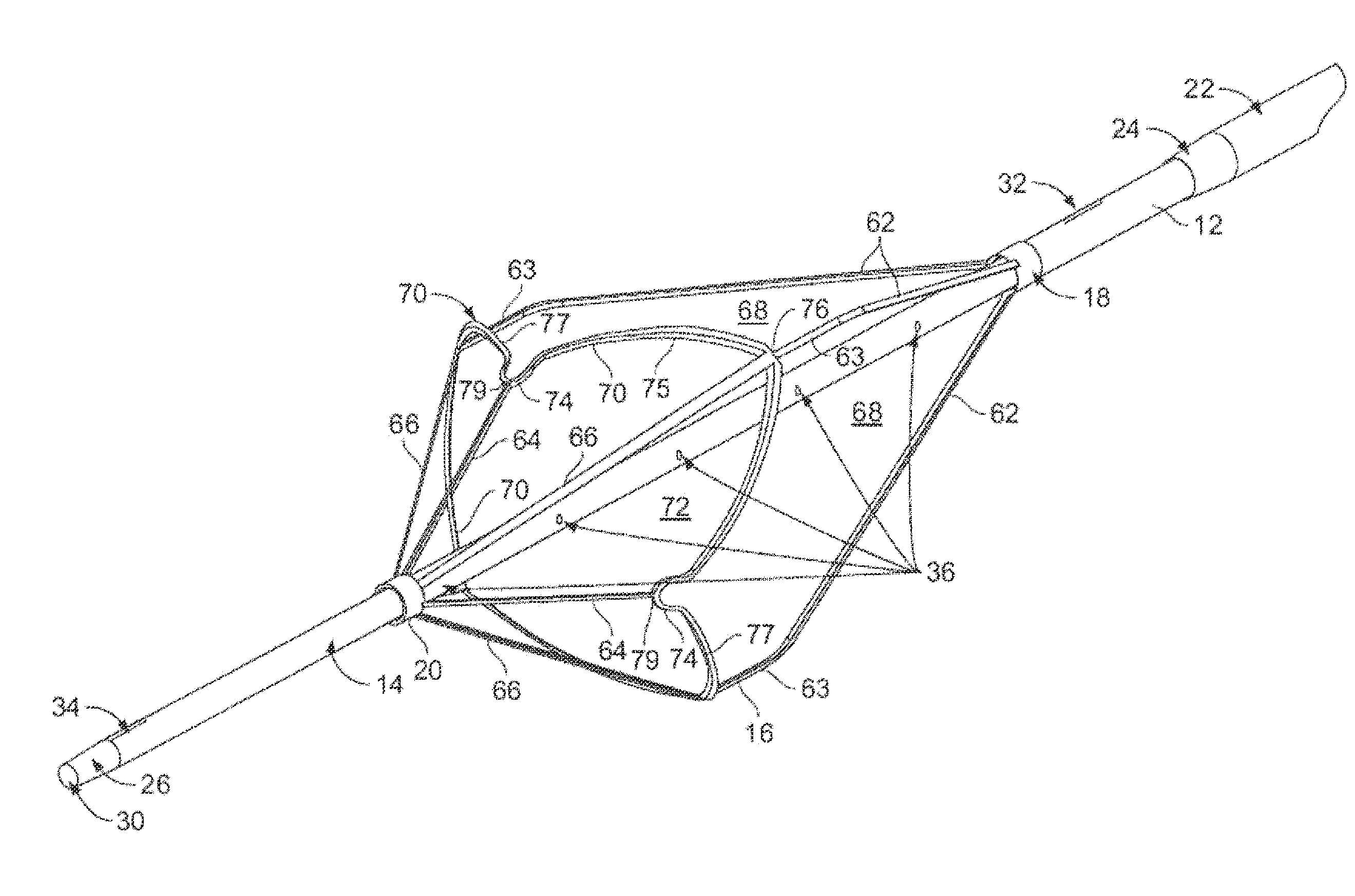
[0006]In view of the above, filters are provided for trapping thrombi in a blood vessel while minimizing the risk of injury to the blood vessel wall. In an example implementation, a filter comprises a frame formed by a plurality of frame members extending from a frame end to a plurality of basket fixation elements. A soft basket comprised of netting surrounding an inner basket region is attached to the frame using a plurality of basket attachment portions attached to corresponding basket fixation elements. The inner basket region of the netting is closed at a distal end by a distal basket closure.

Problems solved by technology

In therapeutic vascular procedures, liberation of embolic debris (e.g., thrombus, clot, atheromatous plaque, etc.) can obstruct perfusion of the downstream vasculature, resulting in cellular ischemia and / or death.
Additionally, percutaneous transluminal coronary angioplasty with or without adjunctive stent placement, surgical coronary artery by-pass grafting, percutaneous renal artery revascularization, and endovascular aortic aneurysm repair have also been associated with complications attributable to atheromatous embolization.
The placement of embolic protection devices typically occurs concomitantly with central access line placement or in critically ill patients that already have a central access line in place.
Additionally, the design of these filters results in increased contact with the vessel wall as the vessel diameter decreases in size, increasing risk of injury to the vessel wall.

Method used


Image

  • Covered filter catheter apparatus and method of using same
  • Covered filter catheter apparatus and method of using same
  • Covered filter catheter apparatus and method of using same

Examples


first embodiment

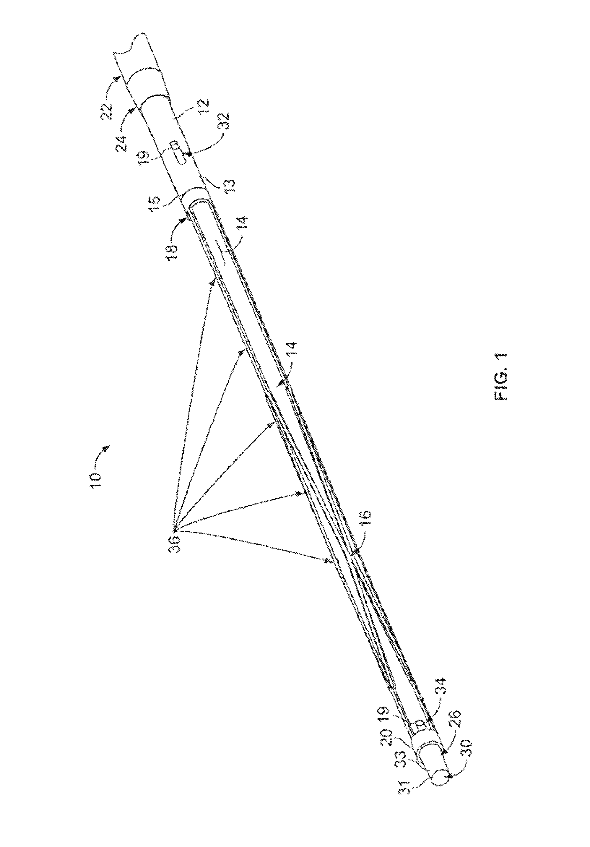
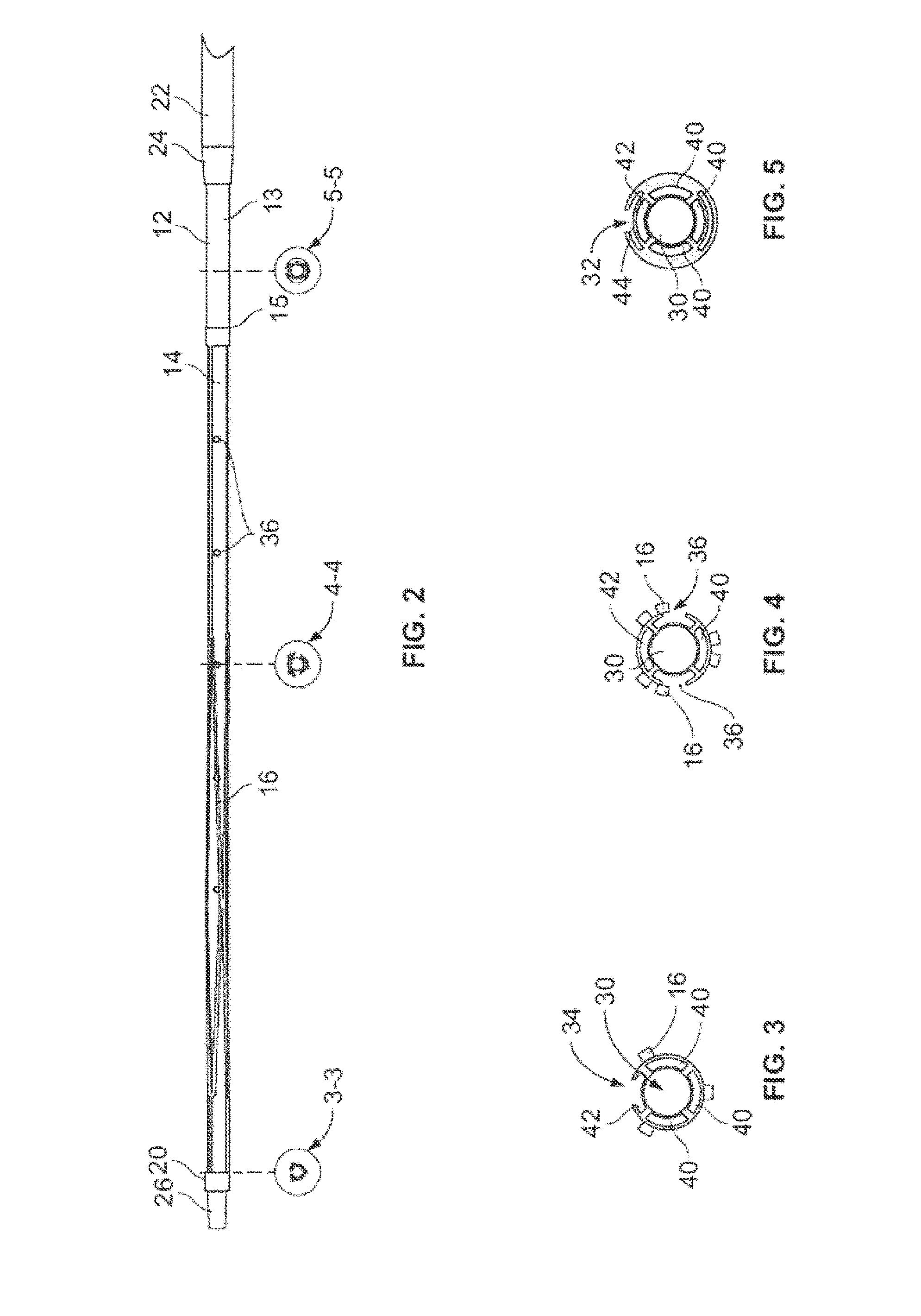
[0056]In the accompanying Figures like structural or functional elements are designated by like reference numerals, e.g., 16, 116, 216, 316, 416 represent similar structural or functional elements across different embodiments of the invention. With particular reference to FIGS. 1-5, according to the invention, there is disclosed a filter catheter 10 that is composed generally of a multi-lumen central catheter body 12 having a proximal port 32 associated with a first lumen 44 and a distal port 34 associated with a second lumen 42. A filter member 16, having a first end 18 and a second end 20, is positioned generally intermediate the distal port 34 and the proximal port 32 and is generally concentric relative to the catheter body 12. An outer sheath 22 may be concentrically disposed over the catheter body 12 such that relative movement of the catheter body 12 and the outer sheath 22 either exposes the filter member 16 or captures the filter member 16 within the outer sheath 22. The ou...

second embodiment

[0066]FIGS. 6-11 illustrate the filter catheter 50. Unlike filter catheter 10, filter catheter 50 does not include the central guidewire lumen 30 of filter catheter 10. Rather, while the general construct of filter catheter 50 is similar to that of filter catheter 10, a different configuration of the inner lumens is employed.

[0067]Filter catheter 50, like filter catheter 10, consists generally of a multi-lumen catheter body 12 having a proximal port 32 associated with a first lumen 54 and a distal port 34 associated with a second lumen 58, a filter member 16, having a fixed proximal end 18 and a moveable distal end 20, is positioned generally intermediate the distal port 34 and the proximal port 32 and is generally concentric relative to the catheter body 12. Use of the term “generally intermediate” is intended to mean that at least a substantial portion of the filter member 16 resides intermediate the distal port 34 and the proximal port 32. Thus, the filter member 16 may partially...


PUM

PropertyMeasurementUnit
porosityaaaaaaaaaa
porosityaaaaaaaaaa
lengthaaaaaaaaaa

Abstract

A combined catheter and an embolic filter, further including a porous section coupled to at least a distal portion of the filter, wherein the porous section comprises a cover member may comprise high porosity ePTFE, or a netting forming a soft basket.

Description

CROSS-REFERENCE TO RELATED APPLICATIONS[0001]This non-provisional application claims the benefit of the priority of U.S. Provisional Application Ser. No. 61 / 836,069, which was filed on Jun. 17, 2013, and is incorporated by reference herein in its entirety.BACKGROUND OF THE INVENTION[0002]The present invention relates generally to embolic filter devices for placement in the vasculature, and in particular to self-expanding frames used to support embolic filter elements.[0003]Embolic protection is a concept of growing clinical importance directed at reducing the risk of embolic complications associated with interventional (i.e., transcatheter) and surgical procedures. In therapeutic vascular procedures, liberation of embolic debris (e.g., thrombus, clot, atheromatous plaque, etc.) can obstruct perfusion of the downstream vasculature, resulting in cellular ischemia and / or death. The therapeutic vascular procedures most commonly associated with adverse embolic complications include: caro...

Claims


Application Information

Patent Timeline
Patent Type & Authority Applications(United States)
IPC IPC(8): A61F2/01A61L31/14
CPCA61F2/01A61L31/146A61F2002/011A61F2230/0069A61F2230/006A61F2230/0086A61F2210/0071A61F2210/0014A61F2002/016A61F2002/018A61F2230/0006A61F2230/005A61F2230/0067A61F2230/0097A61L31/048A61F2/0103A61F2/011C08L27/12C08L27/18
Inventor MORGAN, JEREMY
Owner BIO2MEDICAL
Why Eureka
Try Eureka