Method and System for Detecting Errors in the Transfer of Data from a Transmitter to At Least One Receiver

a technology of error detection and data transfer, applied in the field of failure to communicate, can solve the problems of unfavorable cases, non-detectability of errors, and the probability of address errors being detected, and achieve the effect of reducing the statistical average residual error probability and worse residual error probability of individual data packets

Active Publication Date: 2014-12-18
SIEMENS AG
View PDF2 Cites 13 Cited by
  • Summary
  • Abstract
  • Description
  • Claims
  • Application Information

AI Technical Summary

Benefits of technology

[0010]An object of the present invention, particularly in the transfer of a multiplicity of data packets with the same F-addresses, is to reduce the statistical average residual error probability, particularly in cases where an unfavorable allocation of the addresses used in the system results in a worse residual error probability of individual data packets.

Problems solved by technology

An address or routing error in these “lower” protocol layers, i.e., outside the aforementioned F-communication data link layer, results in the delivery of a data packet (F-PDU) to the incorrect receiver.
It has become evident that additional errors (data corruption), which occur in the transfer of the message (F-PDU) or the signature (F-CRC) in the case of an implicit protection of the address, can result in specific cases in a non-detectability of the error.
In other words, depending on the address used, the probability of an address error being detected may, in unfavorable cases, be substantially worse than statistically predicted for the error detection method.
Together with the fact that the addresses are frequently constant in industrial communication, the required residual error probabilities cannot therefore often be achieved.

Method used


Image

  • Method and System for Detecting Errors in the Transfer of Data from a Transmitter to At Least One Receiver
  • Method and System for Detecting Errors in the Transfer of Data from a Transmitter to At Least One Receiver
  • Method and System for Detecting Errors in the Transfer of Data from a Transmitter to At Least One Receiver

Examples


Embodiment Construction

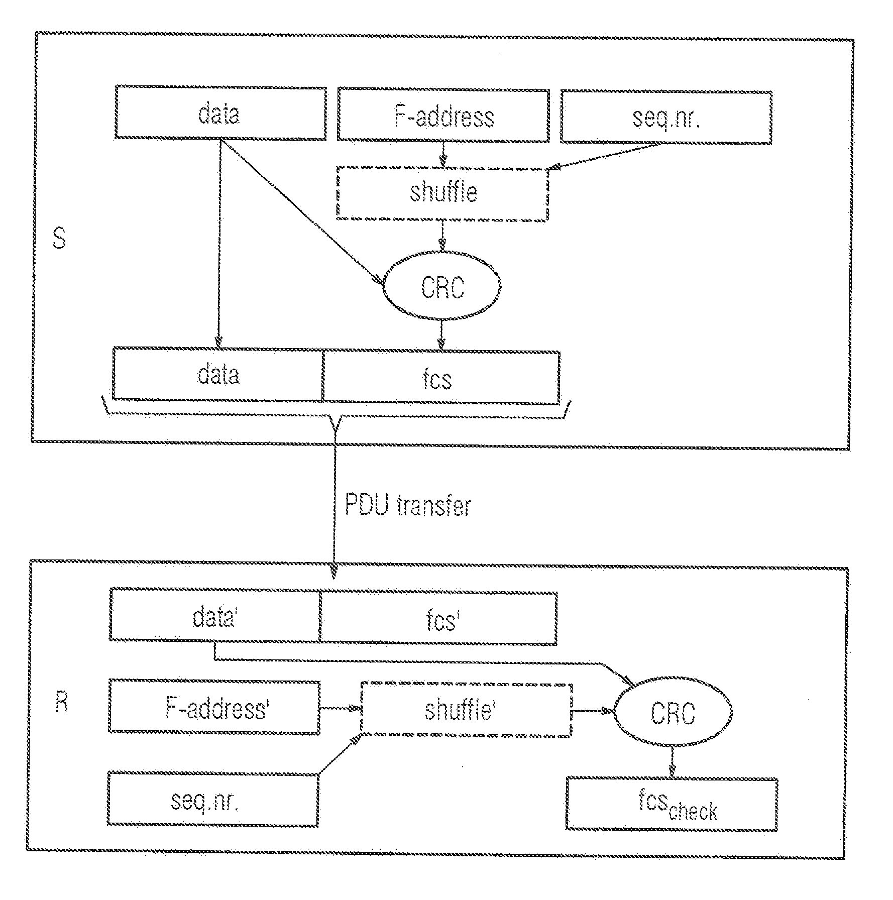
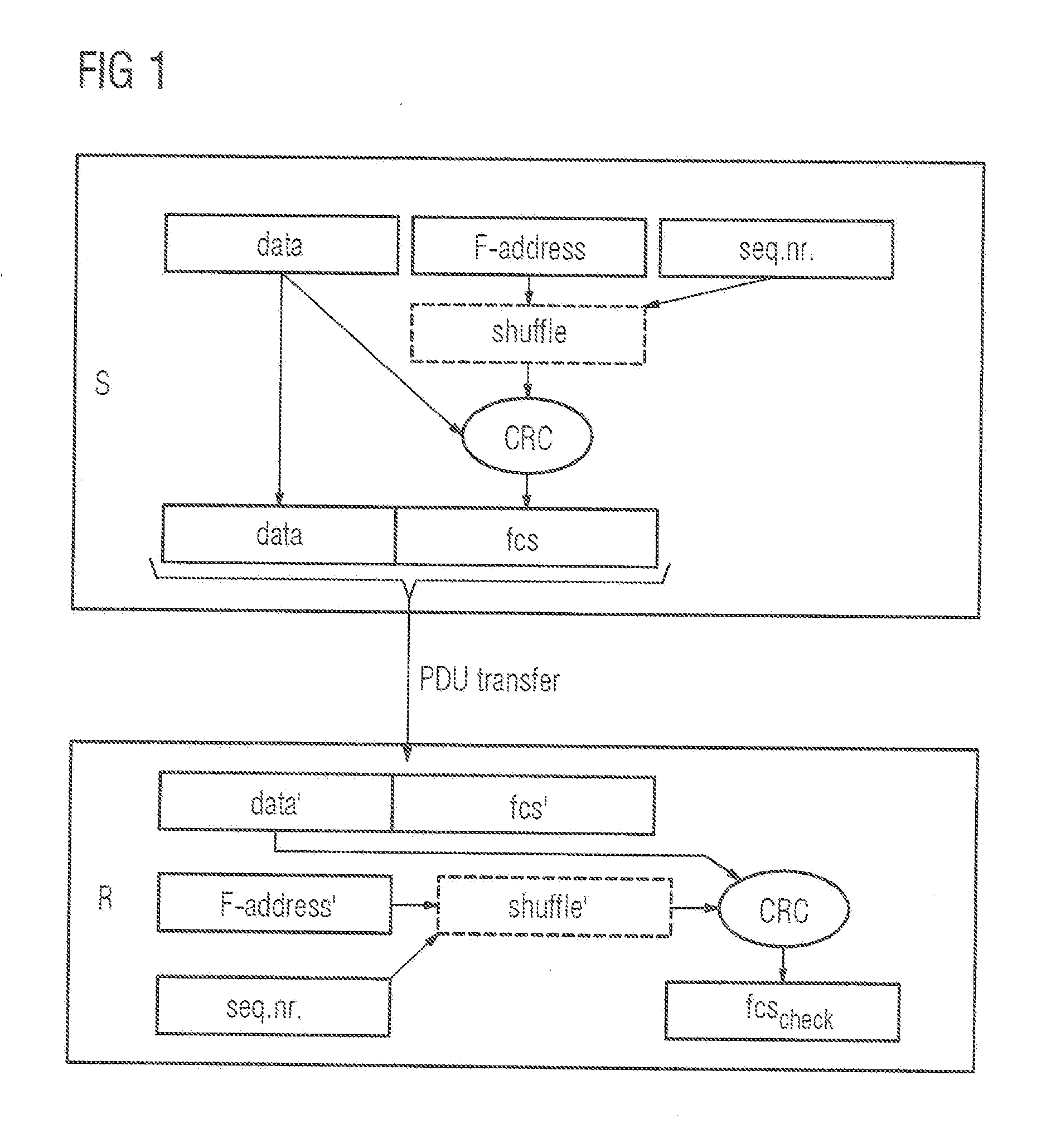
[0033]FIG. 1 shows schematically the generation, transfer and evaluation of a data packet PDU (Process Data Unit). The data packet PDU consists of a data part and a check value FCS (Frame Check Sequence), wherein it is assumed that the data part and the check value FCS are transferred using a known safety-oriented transfer method from the transmitter S to the receiver R (“transfer”). The data part and the check value FCS therefore represent the useful information (“payload”) of a data packet, such as a frame constructed according to the TCP / IP protocol used in the Ethernet.

[0034]The data part, which is intended to he the actual payload of the safe transfer channel, is incorporated unchanged into the safety-oriented data packet in the transmitter S. In addition, a check value FCS is generated which is formed in the present example embodiment using the CRC method (CRC=Cyclic Redundancy Check). However, in the CRC method, the check value FCS is generated from the data part and a number...


PUM


Abstract

A method for detecting errors in a transfer of data from a transmitter to at least one receiver includes coding the data together with address information identifying the receiver in a series of data packets and transferring the data and the address information using the data packets. The method also includes generating, at the transmitter, a check value for each data packet and transferring the check value with/in the data packet to the receiver. The method further includes comparing, at the receiver, the check value with an expectation value, wherein an error is detected in the event of a deviation. For each data packet to be transmitted, the method includes calculating a number sequence value from the address information using a first calculation rule, generating the check value from the sequence value using a second calculation rule and transmitting the data packet with the check value to the receiver.

Description

FIELD OF INVENTION [0001]The invention relates to a system and method for detecting errors in the transfer of data from a transmitter to one or more receivers. Specifically, the invention relates to the technical field of failsafe communication, which is used, inter alia, in the communication between field devices, control components and similar devices in industrial process automation or production automation. A failsafe communication of this type, also referred to as F-communication, is used in particular in safety-related applications, where errors in the communication can result in risks to people, animals or property.DESCRIPTION OF THE RELATED ART[0002]A protected, packet-switched data transfer, in particular the PROFIsafe protocol, is used in the prior art for failsafe communication. Additional check values (checksums, signatures) are used in the “failsafe” data packets (PDU=Process Data Unit), also referred to as “failsafe process data unit” (F-PDU), wherein checksums (FCS—Fr...

Claims


Application Information

Patent Timeline
Patent Type & Authority Applications(United States)
IPC IPC(8): G06F11/10H04L1/00
CPCH04L1/0045G06F11/1004H04L1/0061
Inventor BARTHEL, HERBERTSCHMAUSS, WOLFGANGSIGWART, EDGARWALTER, MAXIMILLIAN
Owner SIEMENS AG
Why Eureka
Try Eureka