Determination of Hysteresis Controller Band for IPMSM-Based Drive System

a technology of hysteresis controller and drive system, which is applied in the direction of electronic commutation motor control, motor/generator/converter stopper, dynamo-electric converter control, etc., can solve the problems of affecting performance, generally not achievable, and complex structure of the oc system

Inactive Publication Date: 2014-12-25
FORD GLOBAL TECH LLC
View PDF3 Cites 4 Cited by
  • Summary
  • Abstract
  • Description
  • Claims
  • Application Information

AI Technical Summary

Benefits of technology

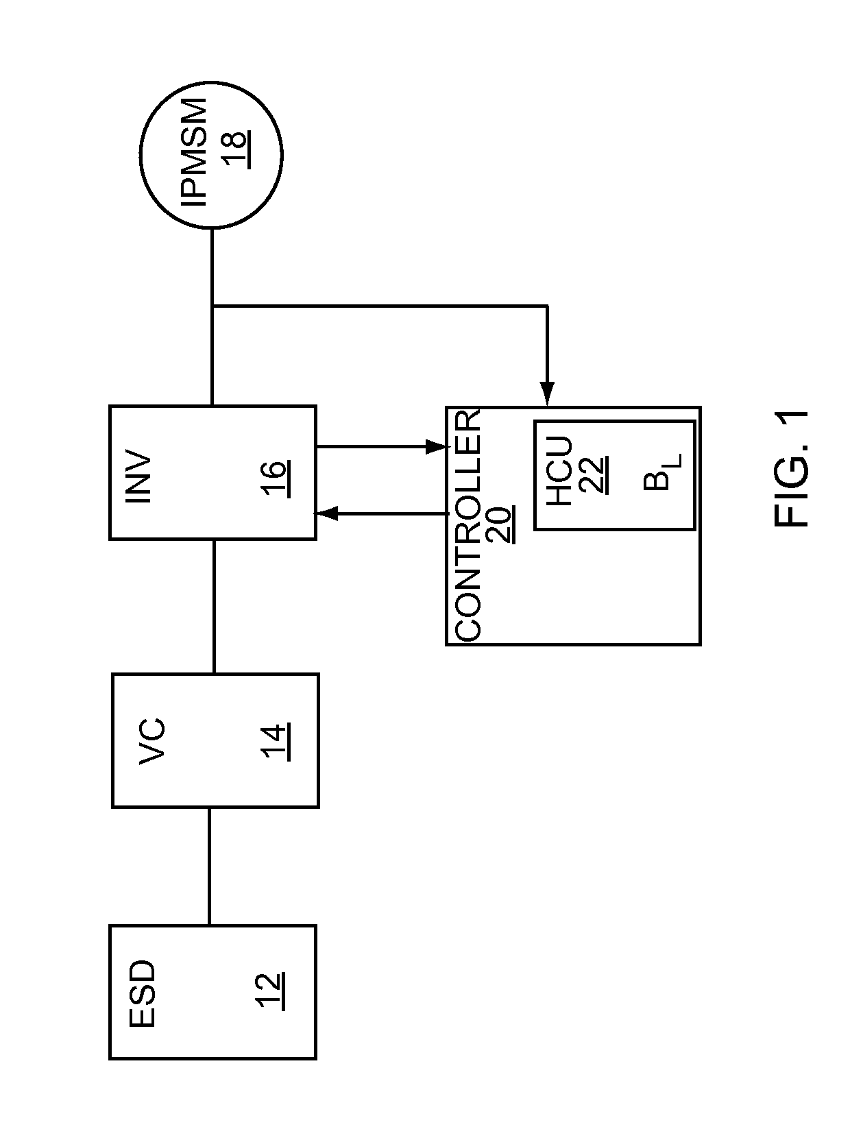
[0011]A system of the invention can include an inverter, an IPMSM and a machine controller configured to control IPMSM operation, wherein the machine controller includes a hysteresis controller having a band based on a machine output variation rate. By way of example, a system can include a hysteresis controller having a band defined by a limit
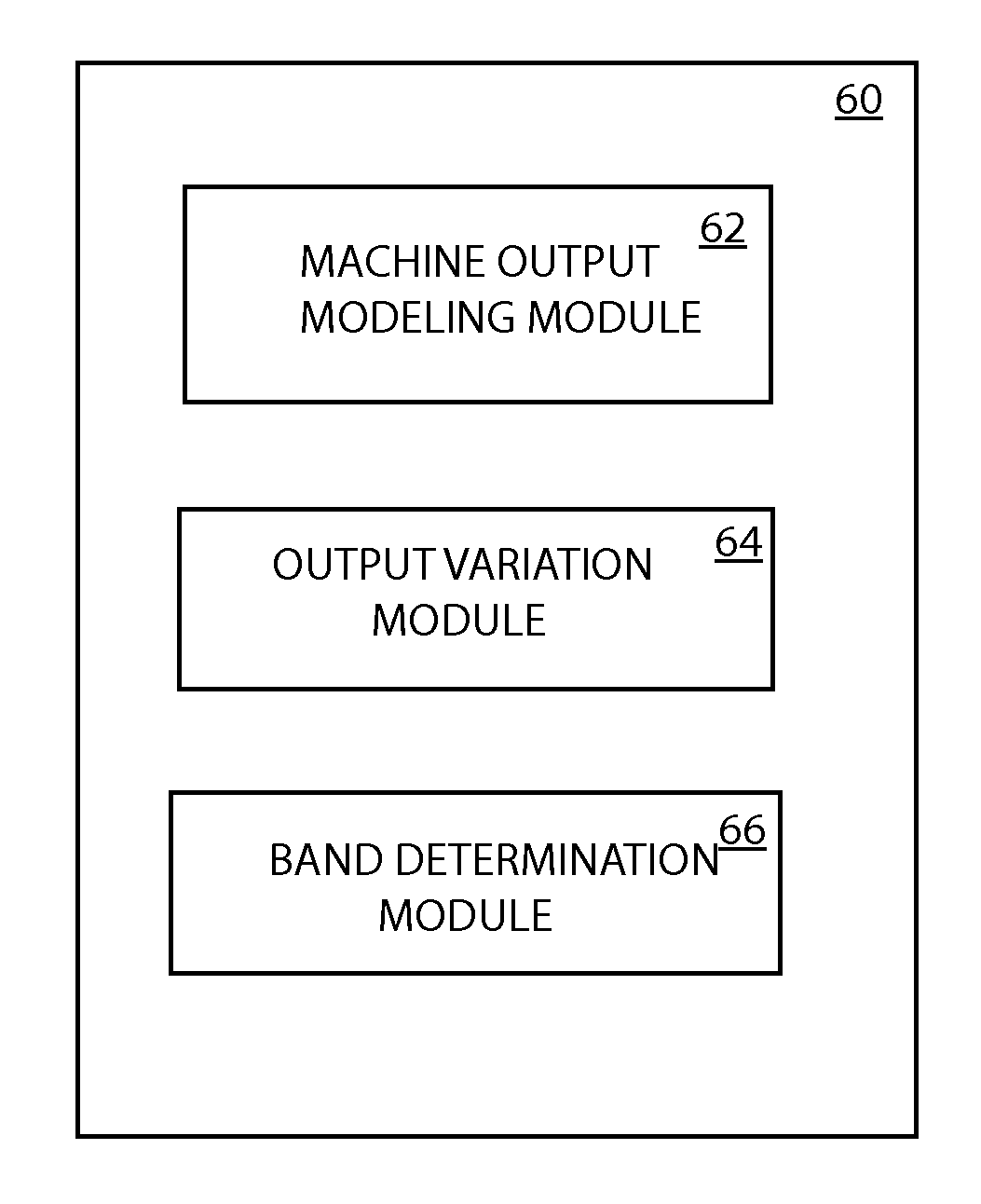
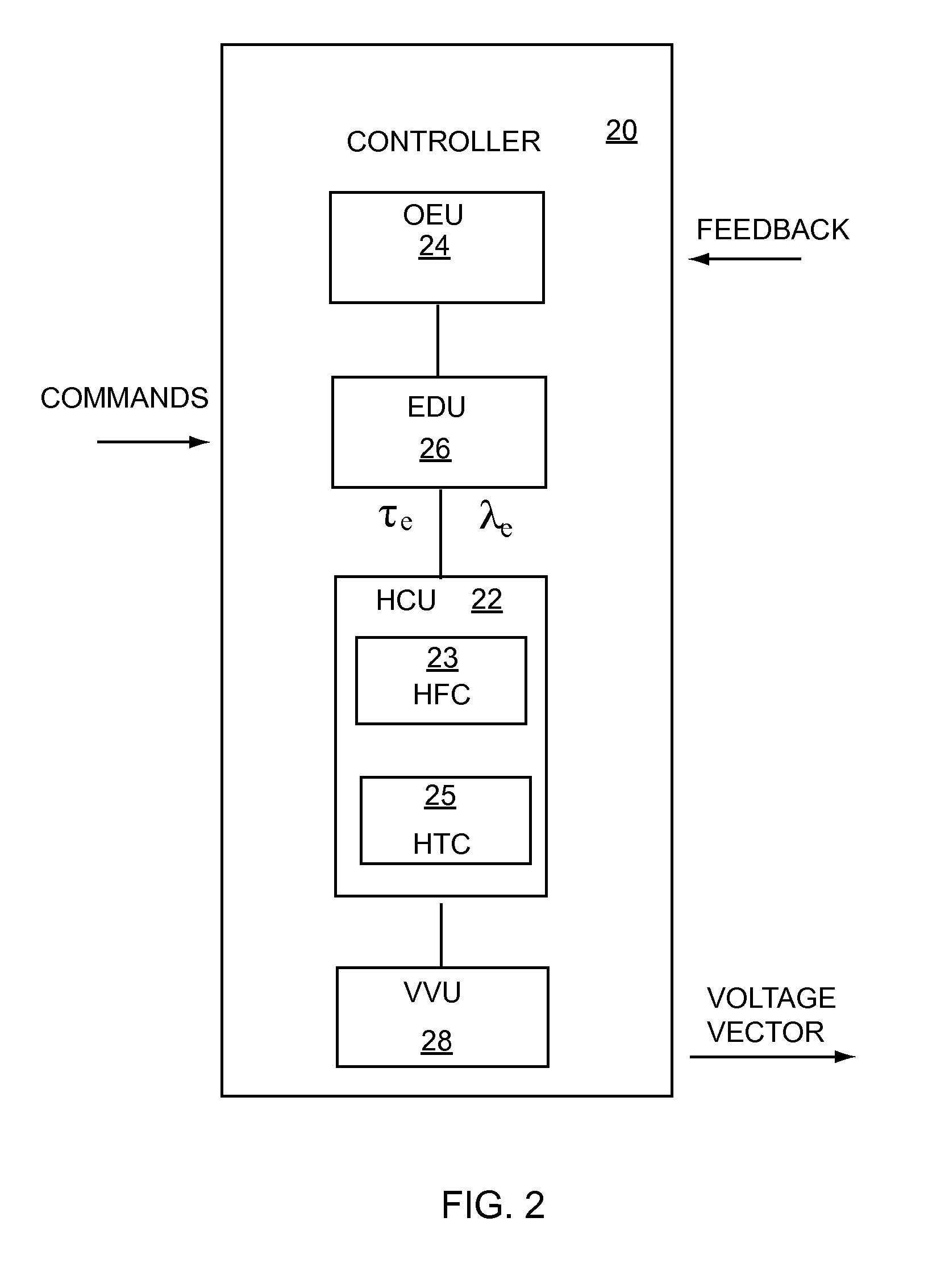
[0012]In an exemplary embodiment, a machine controller can comprise an error detection unit, a hysteresis control unit, a voltage vector unit, and an observation / estimation unit, wherein the hysteresis control unit includes a hysteresis controller having a band based on a machine output variation rate. By way of example, a hysteresis flux controller can have a band defined by a limit

Problems solved by technology

However, FOC systems can be rather complex, requiring continuous rotor position information, current regulators, transformations between rotating and stationary coordinate systems, and pulse width modulation (PWM) generators.
While small bands may be desired for higher machine output accuracy, they are generally not achievable given the physical limitations of drive system components.
On the other hand, large bands, more easily achievable, are prone to noise, vibration and harshness problems which can adversely impact performance and disappoint and / or frustrate an operator.
Unfortunately, there is no universal or standard method for specifying hysteresis controller bands for a particular application.
Instead, determination of controller bands is essentially a trial and error process which can be costly and inefficient.

Method used


Image

  • Determination of Hysteresis Controller Band for IPMSM-Based Drive System
  • Determination of Hysteresis Controller Band for IPMSM-Based Drive System
  • Determination of Hysteresis Controller Band for IPMSM-Based Drive System

Examples


Embodiment Construction

[0031]As required, detailed embodiments of the present invention are disclosed herein. However, it is to be understood that the particular embodiments discussed are merely descriptive examples of the invention, which can be practiced in various and alternative embodiments. The figures are not necessarily to scale, and some features may be exaggerated, minimized or omitted to emphasize details of particular components. Therefore, specific structural and functional details described herein are not to be interpreted as limiting, but merely as a representative basis for teaching one skilled in the art to variously employ the invention. The invention comprehends various aspects of hysteresis band modeling and its various applications.

[0032]Systems and methods of the invention can be practiced to determine and implement a controller band for a hysteresis controller in a direct torque control (DTC) electric machine system. The invention can be used in the design and implementation of elect...


PUM


Abstract

Methods of providing a control band for a hysteresis controller are presented. A method can determine a control band analytically to avoid the time and costs associated with manual calibration of a hysteresis controller. By way of example, a method can include modeling a machine output, such as stator flux or machine torque, modeling the variation rate for the machine output, and providing a control band based on the variation rate modeling.

Description

FIELD OF INVENTION[0001]This invention relates generally to direct torque control (DTC) for an electric machine (IPMSM), and more particularly to a method for determining a DTC hysteresis controller band.BACKGROUND[0002]The demand for electric and hybrid electric vehicles continues to grow as governmental agencies, private organizations and individual consumers strive to conserve resources, reduce energy costs and lower carbon emissions. Electrified vehicles have an electric drive system that includes an electrical machine to assist or replace the internal combustion engine of a conventional vehicle, a power conversion system configured to provide energy to the electric machine, and a machine controller configured to control machine operation. Due to its high power / torque density, its high efficiency, and its high reliability, a permanent magnet synchronous motor (PMSM) is a popular choice for electric vehicle drive systems. Most machine controllers used with PMSMs in electric vehic...

Claims


Application Information

Patent Timeline
Patent Type & Authority Applications(United States)
IPC IPC(8): H02P7/00
CPCH02P7/00H02P27/12H02P21/30
Inventor WANG, CHIANG-JIANGDEGNER, MICHAEL
Owner FORD GLOBAL TECH LLC
Why Eureka
Try Eureka