Stereo scopic video coding device, steroscopic video decoding device, stereoscopic video coding method, stereoscopic video decoding method, stereoscopic video coding program, and stereoscopic video decoding program

a video coding and coding method technology, applied in signal generators with optical-mechanical scanning, color televisions with bandwidth reduction, television systems, etc., can solve the problems of large amount of data, difficult to put into practical use, and uncomfortable feeling, so as to reduce the amount of data and reduce the amount of overlooking. , the effect of high efficiency

Inactive Publication Date: 2014-12-25
NAT INST OF INFORMATION & COMM TECH
View PDF5 Cites 17 Cited by
  • Summary
  • Abstract
  • Description
  • Claims
  • Application Information

AI Technical Summary

Benefits of technology

[0119]With the first, twelfth, or fourteenth aspect of the invention, when the reference viewpoint video, the auxiliary viewpoint video, and respective depth maps corresponding thereto are encoded, a depth map at an intermediate viewpoint between the reference viewpoint and the auxiliary viewpoint is selected as data to be encoded on the depth map. Also, a residual video created by extracting only a pixel to become an occlusion hole which is not projectable from the reference viewpoint video is selected as data to be encoded on the auxiliary viewpoint video. This reduces respective amounts of the data, thus allowing encoding at a high efficiency compared to their original data amounts.
[0120]With the second aspect of the invention, a pixel to become an occlusion hole can be detected with less overlooking. Thus, when a result of the detection is used for segmenting a pixel of the auxiliary viewpoint video and thereby creating a residual video, a pixel required for creating a video at an arbitrary viewpoint by the stereoscopic video decoding device can be segmented appropriately.
[0121]With the third aspect of the invention, the expansion of a hole mask indicating a position of a pixel to become an occlusion hole can reduce overlooking of such a pixel to become an occlusion hole. Thus, when a result of the detection is used for segmenting a pixel of the auxiliary viewpoint video and thereby creating a residual video, a pixel required for creating a video at an arbitrary viewpoint by the stereoscopic video decoding device can be segmented further appropriately.
[0122]With the fourth aspect of the invention, in addition to using a depth map at the auxiliary viewpoint, an occlusion hole is detected using an intermediate viewpoint depth map which is a depth map at the intermediate viewpoint, which allows a further appropriate detection of a pixel to become an occlusion hole. Thus, a result of the detection can be used for creating a further appropriate residual video.
[0123]With the fifth aspect of the invention, in addition to using a depth map at the auxiliary viewpoint, an occlusion hole is detected using a depth map at the specified viewpoint used when an encoded data is decoded and a multi-view video is created on a decoding side. Thus, a result of the detection can be used for creating a further appropriate residual video.
[0124]With the sixth aspect of the invention, each of the intermediate viewpoint depth map and the depth map between a plurality of viewpoints are framed, which allows an amount of data to be reduced. This makes it possible for the stereoscopic video encoding device to encode the data at a high efficiency.

Problems solved by technology

Viewers may feel uncomfortable due to absence of motion parallax or may have eyestrain or the like because of wearing special glasses.
The multi-view video requires, however, transmitting and storing a large number of viewpoint videos, resulting in large quantity of data, which makes it difficult to put into practical use.

Method used


Image

  • Stereo scopic video coding device, steroscopic video decoding device, stereoscopic video coding method, stereoscopic video decoding method, stereoscopic video coding program, and stereoscopic video decoding program
  • Stereo scopic video coding device, steroscopic video decoding device, stereoscopic video coding method, stereoscopic video decoding method, stereoscopic video coding program, and stereoscopic video decoding program
  • Stereo scopic video coding device, steroscopic video decoding device, stereoscopic video coding method, stereoscopic video decoding method, stereoscopic video coding program, and stereoscopic video decoding program

Examples


first embodiment

Stereoscopic Video Transmission System

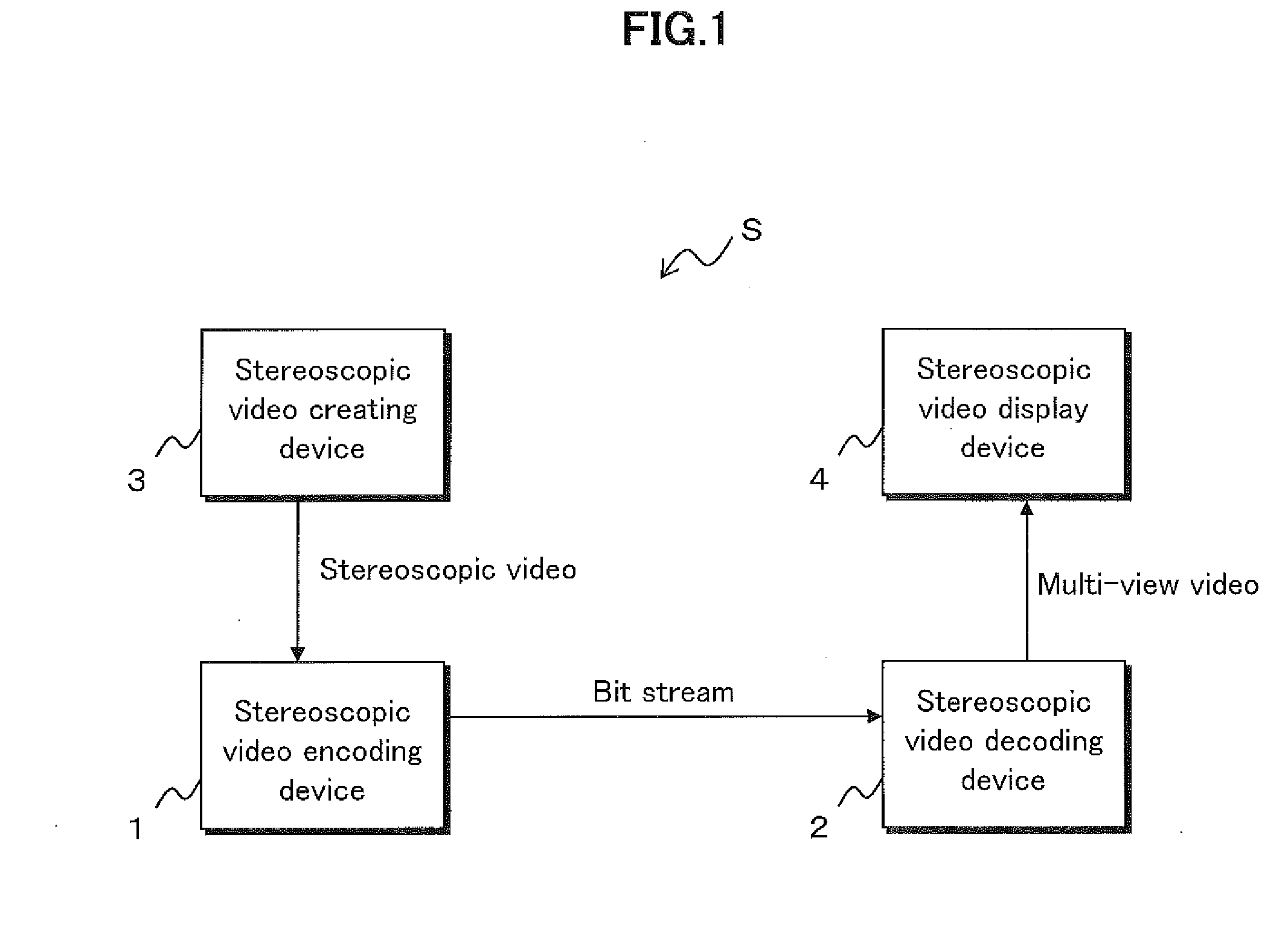
[0176]With reference to FIG. 1 is described a stereoscopic video transmission system S including a stereoscopic video encoding device and a stereoscopic video decoding device according to a first embodiment of the present invention.

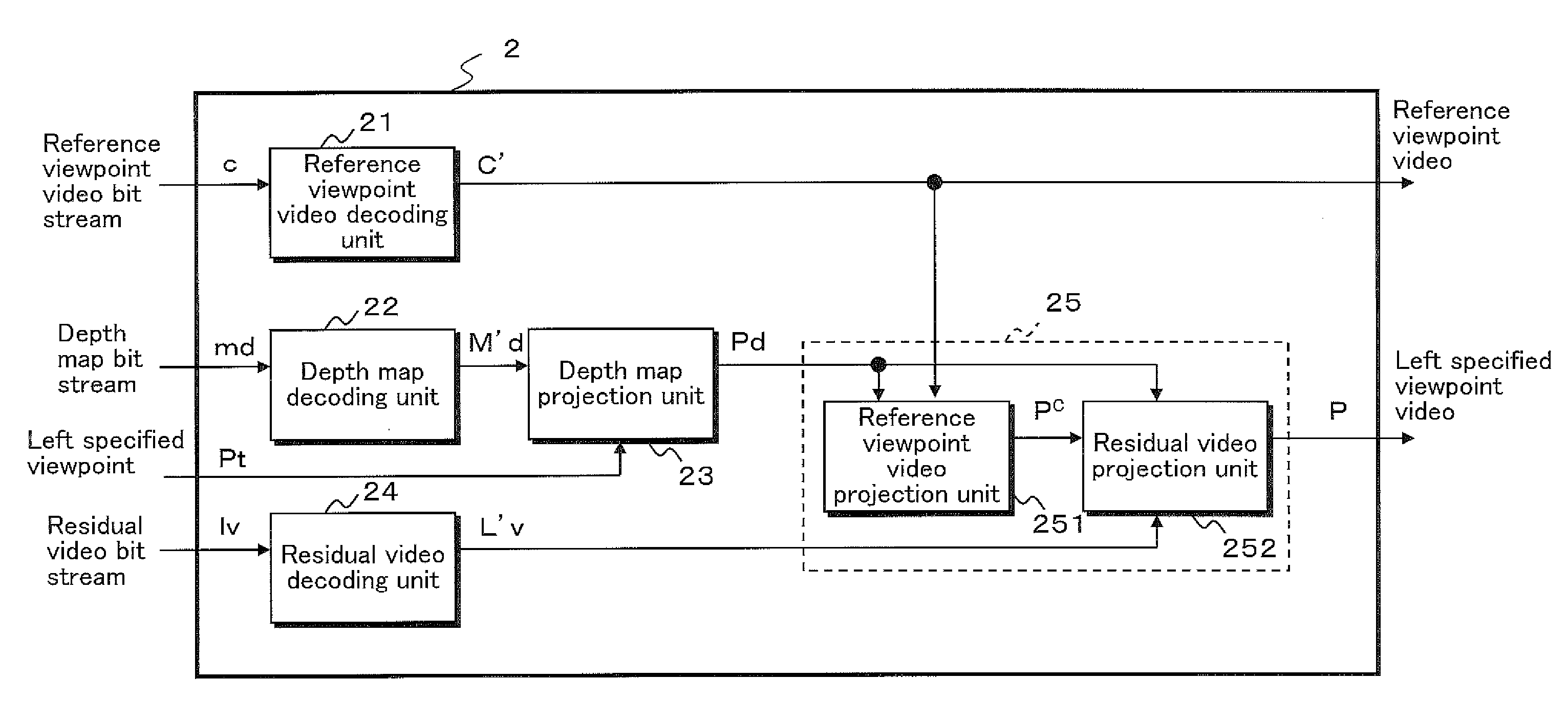
[0177]The stereoscopic video transmission system S encodes a stereoscopic video taken by a camera or the like, transmits the encoded stereoscopic video together with a depth map corresponding thereto, to a destination, and creates a multi-view video at the destination. The stereoscopic video transmission system S herein includes a stereoscopic video encoding device 1, a stereoscopic video decoding device 2, a stereoscopic video creating device 3, and a stereoscopic video display device 4.

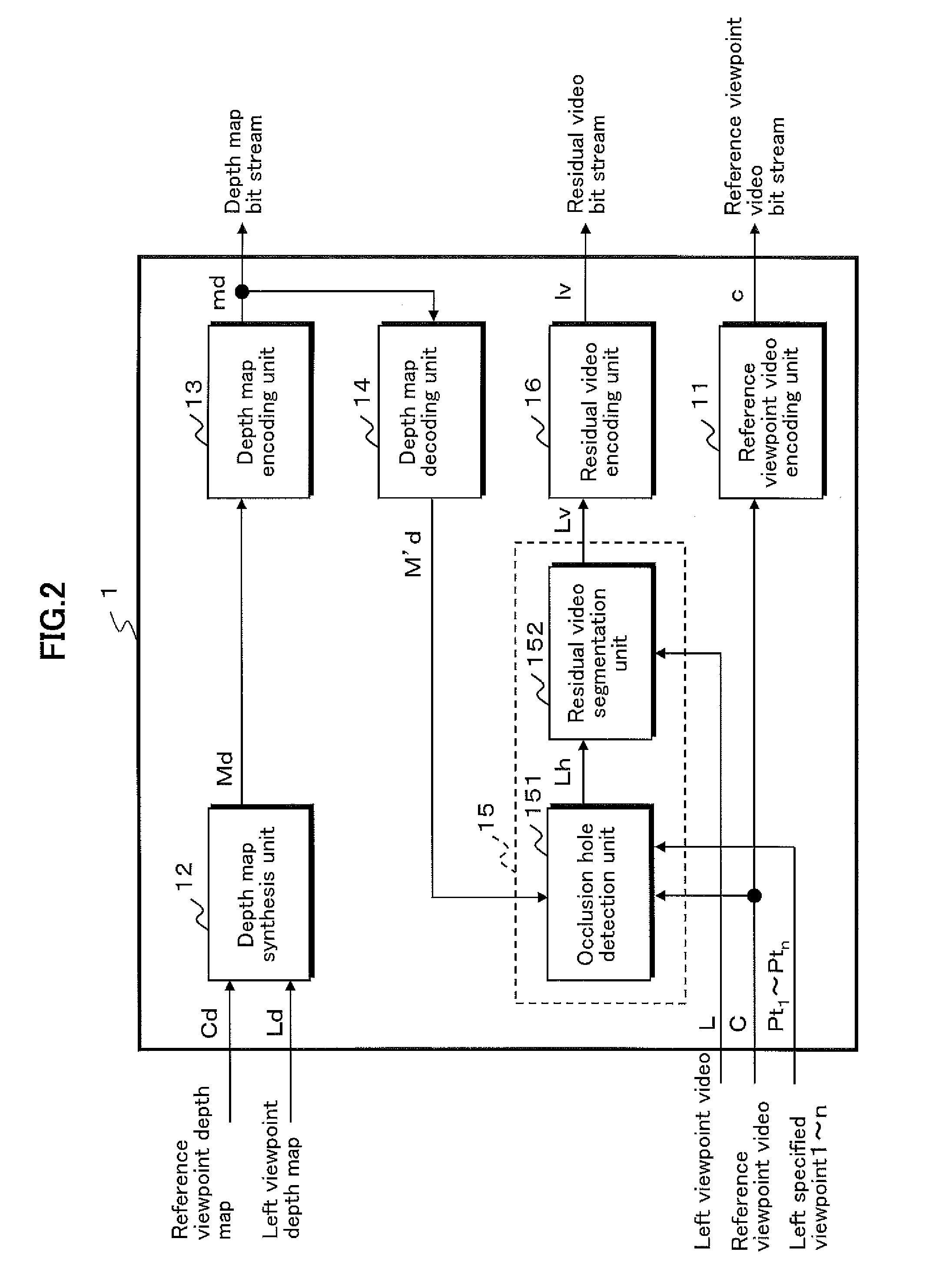
[0178]The stereoscopic video encoding device 1 encodes a stereoscopic video created by the stereoscopic video creating device 3, outputs the encoded stereoscopic video as a bit stream to a transmission path, and thereby transmits the ...

second embodiment

Variation of Second Embodiment

[0394]Next are described a stereoscopic video encoding device and a stereoscopic video decoding device according to a variation of the second embodiment of the present invention.

[0395]In the stereoscopic video encoding device according to this variation, when the depth map framing unit 17 and the residual video framing unit 19 of the encoding device 1A according to the second embodiment illustrated in FIG. 12 reduce a depth map and a residual video, respectively, each of the depth map framing unit 17 and the residual video framing unit 19: thins out pixels thereof in a lateral direction for reducing a width to half; and joins a pair of the reduced depth maps and a plurality of the residual videos side by side, respectively, into a single framed image, as illustrated in FIG. 18A and FIG. 18B.

[0396]The stereoscopic video encoding device according to this variation is configured such that the depth map separation unit 18 of the encoding device 1A separates...

third embodiment

Variation of Third Embodiment

[0542]Next are described a stereoscopic video encoding device and a stereoscopic video decoding device according to a variation of the third embodiment of the present invention.

[Configuration of Stereoscopic Video Encoding Device]

[0543]A configuration of the stereoscopic video encoding device according to this variation is described with reference to FIG. 19 and FIG. 21B.

[0544]The stereoscopic video encoding device (which may also be simply referred to as an “encoding device 1C” where appropriate, though an entire configuration thereof is not shown) according to this variation is similar to the projected video prediction unit 15B of the encoding device 1B according to the third embodiment illustrated in FIG. 19 except that the stereoscopic video encoding device 1C creates the left residual video Lv by calculating, for each of pixels of a video of interest, a difference of pixel values between the left viewpoint video L and a video in which the decoding r...


PUM


Abstract

A stereoscopic video coding device inputs therein a reference viewpoint video and a left viewpoint video, as well as a reference viewpoint depth map and a left viewpoint depth map which are maps showing information on depth values of the respective viewpoint videos. A depth map synthesis unit of the stereoscopic video coding device creates a left synthesized depth map at an intermediate viewpoint from the two depth maps. A projected video prediction unit of the stereoscopic video coding device extracts, from the left viewpoint video, a pixel in a pixel area to constitute an occlusion hole when the reference viewpoint video is projected to another viewpoint and creates a left residual video. The stereoscopic video coding device encodes and transmits each of the reference viewpoint video, the left synthesized depth map, and the left residual video.

Description

TECHNICAL FIELD[0001]The present invention relates to: a stereoscopic video encoding device, a stereoscopic video encoding method, and a stereoscopic video encoding program, each of which encodes a stereoscopic video; and a stereoscopic video decoding device, a stereoscopic video decoding method, and a stereoscopic video decoding program, each of which decodes the encoded stereoscopic video.BACKGROUND ART[0002]Stereoscopic televisions and movies with binocular vision have become popular these years. Such televisions and movies, however, realize not all of factors required for stereoscopy. Viewers may feel uncomfortable due to absence of motion parallax or may have eyestrain or the like because of wearing special glasses. There is thus a need for putting into practical use a stereoscopic video with naked eye vision closer to natural vision.[0003]The naked-eye stereoscopic video can be realized by a multi-view video. The multi-view video requires, however, transmitting and storing a l...

Claims


Application Information

Patent Timeline
Patent Type & Authority Applications(United States)
IPC IPC(8): H04N19/597H04N19/51
CPCH04N19/00696H04N19/00769H04N19/597H04N13/111H04N13/161H04N13/194H04N2213/005
Inventor SENOH, TAKANORIICHIHASHI, YASUYUKISASAKI, HISAYUKIYAMAMOTO, KENJIOI, RYUTAROKURITA, TAIICHIRO
Owner NAT INST OF INFORMATION & COMM TECH
Why Eureka
Try Eureka