Small aperture (pinhole) intraocular implant to increase depth of focus

a small aperture, intraocular implant technology, applied in the field of ophthalmology, can solve the problems of reducing contrast sensitivity and optical quality, affecting the effect of contrast, and reducing the effect of aberration, so as to promote an improvement in visual acuity, improve the depth of focus, and minimize the impact of aberration

Inactive Publication Date: 2014-12-25
TRINDADE CLAUDIO
View PDF3 Cites 29 Cited by
  • Summary
  • Abstract
  • Description
  • Claims
  • Application Information

AI Technical Summary

Benefits of technology

[0021]In view of the above, the invention's main objective is to provide an intraocular implant to a person who has undergone cataract surgery with implantation of a standard intraocular lens, whereby the implant provides an increased depth of focus, allowing both near vision as far. Another objective of this invention is to minimize the impact of aberrations of low and high-order visual quality, thus promoting an improvement in visual acuity. Yet another objective is to eliminate the need for glasses by extending the depth of focus of a monofocal intraocular lens.

Problems solved by technology

Because it is an artificial lens, it has no mechanism for adjusting the focus to different distances.
These models promote fair spectacle independence, but causes reduced contrast sensitivity and optical quality, in addition, optical phenomena such as halos and glare can cause loss of visual acuity.
This procedure has several limitations, such as lack of knowledge about long-term biocompatibility of the implant material, need to perform a surgery on a perfectly normal structure, among others.
Furthermore it blocks the viewing of other intraocular structures and may hinder future ophthalmic surgery such as cataract surgery case, and may even hinder routine examination of the interior of the eye.

Method used


Image

  • Small aperture (pinhole) intraocular implant to increase depth of focus
  • Small aperture (pinhole) intraocular implant to increase depth of focus
  • Small aperture (pinhole) intraocular implant to increase depth of focus

Examples


first embodiment

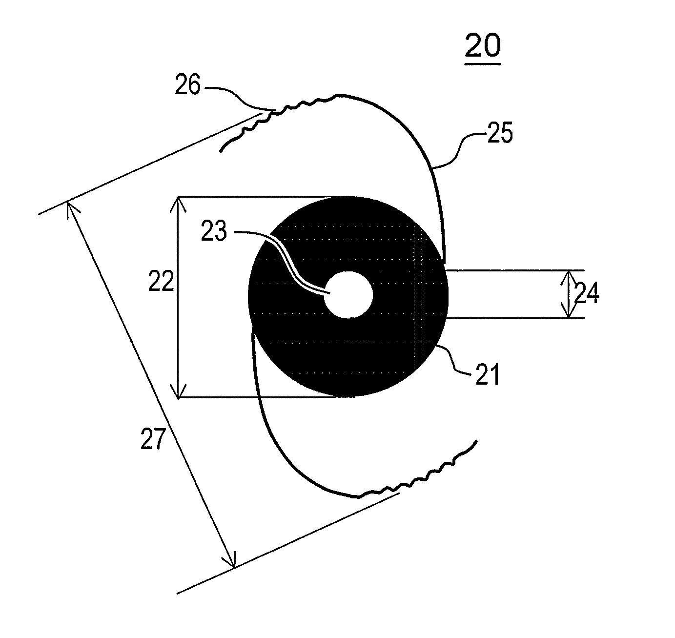
[0053]An embodiment of an implant according to the invention is described below in detail through exemplary achievements. Details are illustrated in FIGS. 2 and 5, which represent the invention.

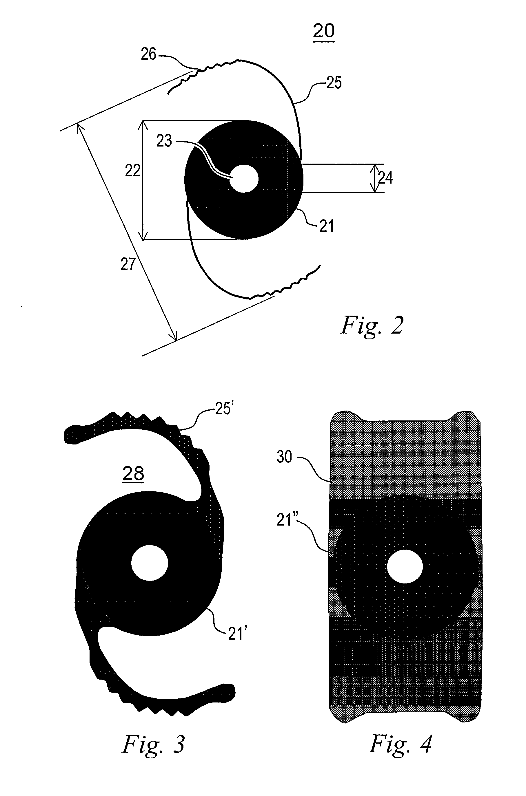
[0054]Anintraocular implant comprises a body 20 shaped like a concave-convex diaphragm 21, made of rigid or flexible material, preferably flexible, the material or a coating or coloring layer is opaque to visible light, preferably black colored material or a black coating 22 with a diameter of between 4 mm and 7 mm, preferably between 5.5 mm and 6.5 mm.

[0055]In its central region a passage means 23 for visible light rays with a diameter 24 of between 1 mm and 2.5 mm, preferably between 1.4 mm and 2.0 mm is arranged, which allows a passage of light rays which, due to the pinhole effect, are sharply focused on the retina, inversely proportional to the diameter of the passage. The thickness of said diaphragm is between 100 μm and 900 μm, preferably between 200 μm and 400 μm.

[0056]Said pinhole ef...

second embodiment

[0069]Considering an implant configured illustrated in FIGS. 3 and 6, the most suitable materials for the whole-body handles 25′ would hydrophilic acrylic, hydrophobic acrylic, silicone and / or PMMA, preferably hydrophilic acrylic.

third embodiment

[0070]Further, an implant configured illustrated in FIGS. 4 and 7, suitable materials for the platform 30 would be silicone, acrylic hydrophobic and hydrophilic acrylic, preferably silicone.

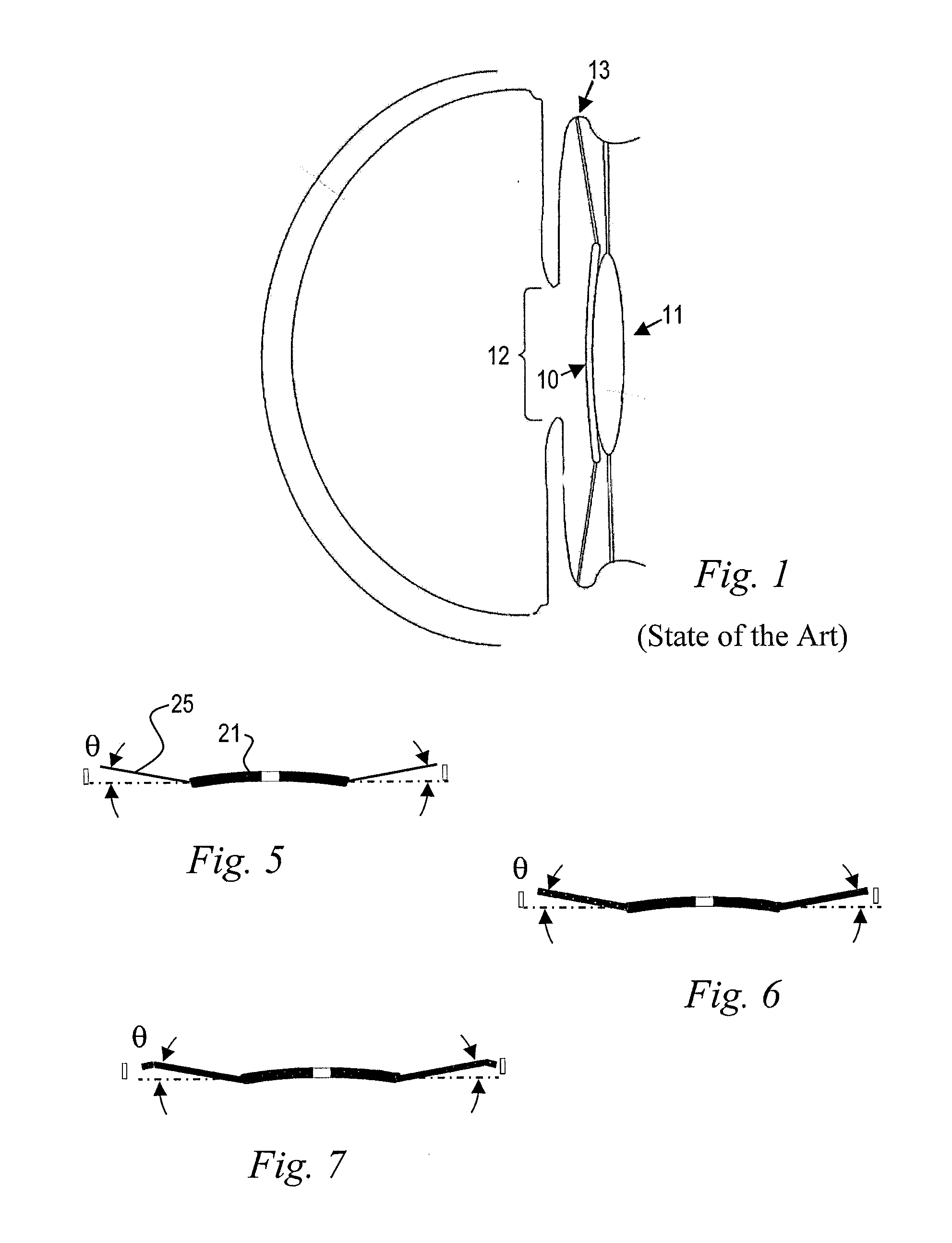
[0071]In FIG. 8 an embodiment of an implant with a circular diaphragm 21 with hole 23 and four handles 25 is depicted. The implant of FIG. 8 is a modification of the embodiment of FIG. 3. The handles 25 can also comprise an undulated or zigzag distal end part 26 for improving fastening characteristics and flexibility. Another embodiment can also comprise three or five handles 23.

[0072]In FIGS. 9 and 10 further embodiments of an implant according to the invention are displayed. The implant comprises a diaphragm 21 being opaque to visible light and transparent to IR-light with a circular hole 23 in its center and two, three, four or even more loops 31. The loops 31 are formed in a bended curvature and both ends of each loop 31 is attached to diaphragm 21. Thus a lightweight and securely fastening ...


PUM


Abstract

Small aperture (pinhole) intraocular implant to increase depth of focus comprising a diaphragm juxtaposed to the front surface of a lens implanted previously, having its anterior surface convex and its posterior surface concave. The diaphragm is held in position by inserting engaging means in the ciliary sulcus.
It is proposed that said diaphragm is opaque to a visible light spectrum and transparent to light in the infrared range and is equipped with passage means of visible light in its central region, such as a through hole whose diameter is between 1 mm and 2.5 mm.
The constriction of the incident light rays increases the depth of focus, featuring a pinhole effect. The engagement means may be provided by two handles shaped with curved proximal ends joined to the peripheral edge of said diaphragm and having substantially circular section with a diameter between 80 μm and 800 μm or two handles of the same material as the diaphragm and constituting an extension of this edge, or even one elongated platform whose center is located in the small-diameter circular opening.

Description

FIELD OF APPLICATION [0001]The present invention applies to the field of ophthalmology, and more specifically to the field of cataract surgery. It is an attempt to promote increased visual performance after implantation of an intraocular lens.[0002]For a better understanding of this specification, we present below some technical terms used in the same:[0003]Lens:—is an intraocular lens which is located between the iris and the vitreous humor. For full operation of the eye, a full transparency of said lens is required. This characteristic is achieved due to the absence of blood vessels and the compression of the plates that constitute it. The dimensions of the lens vary throughout life, with slow growth due to the constant formation of new lamellae.[0004]Cataract:—is an eye disease that causes a loss of transparency of the lens, which can be triggered by several factors, including advanced age, ocular trauma, diabetes mellitus, uveitis, use of drugs, among other causes, causes a prog...

Claims


Application Information

Patent Timeline
Patent Type & Authority Applications(United States)
IPC IPC(8): A61F2/16
CPCA61F2/1659A61F2/1613A61F2/15A61F2002/1699
Inventor TRINDADE, CLAUDIO
Owner TRINDADE CLAUDIO
Why Eureka
Try Eureka