
Pump efficiency determining system and related method for determining pump efficiency

a pump efficiency and efficiency determining technology, applied in the field of pump efficiency determining system and related methods for determining pump efficiency, can solve the problems of inability to detect operating problems, inability to maximize and inability to operate at maximum efficiency of the pump, so as to improve the chances of optimal performance, maintain the overall system efficiency and performance, and improve the efficiency of the pump. the effect of cost and labor

Inactive Publication Date: 2014-12-25
GHD PTY LTD
View PDF8 Cites 56 Cited by
  • Summary
  • Abstract
  • Description
  • Claims
  • Application Information

AI Technical Summary

Benefits of technology

The system and method described in this patent have the benefits of being able to make early and proactive decisions to improve the performance of pumps in manufacturing or processing facilities. It can be easily retrofitted into existing facilities and capture data on pump efficiency in real-time, using a hydraulic method. This allows for the calculation and analysis of pump efficiency within a system, regardless of the brand or model of pump used. By monitoring pump performance, the system can also make adjustments or replacements in a proactive manner to maintain overall system efficiency and performance, improve cost and labor, and avoid potentially catastrophic events.

Problems solved by technology

Pumping systems that are used in a range of industries, including the water, power and oil sectors, may not operate at maximum efficiency due to damaged and worn impellers, pitted volutes, bad motor windings, poor couplings and poorly commissioned pump controls, among other factors.
In most of the foregoing situations, these operating issues cannot be visibly detected and in fact may not be discovered until after the pump has already been taken out of service for scheduled maintenance, or until the problem has exacerbated to the point in which a severe or catastrophic failure has occurred.
Pumps represent a significant portion of the pumping facility energy and life cycle costs and are often critical components of a process (manufacturing or otherwise).
Efficiency of pumps using this system, however, such as reciprocating and centrifugal pumps, is impractical to calculate where pumps are operating at variable speed and existing market products using this method are not configured for variable speed operation.
In addition, thermodynamic based systems are unable to estimate heat transfer in non-fluid mediums such as bearings and pump casings.
Therefore, the larger the pump, the more likely this type of system is going to be inaccurate.

Method used


Image

  • Pump efficiency determining system and related method for determining pump efficiency
  • Pump efficiency determining system and related method for determining pump efficiency
  • Pump efficiency determining system and related method for determining pump efficiency

Examples


Embodiment Construction

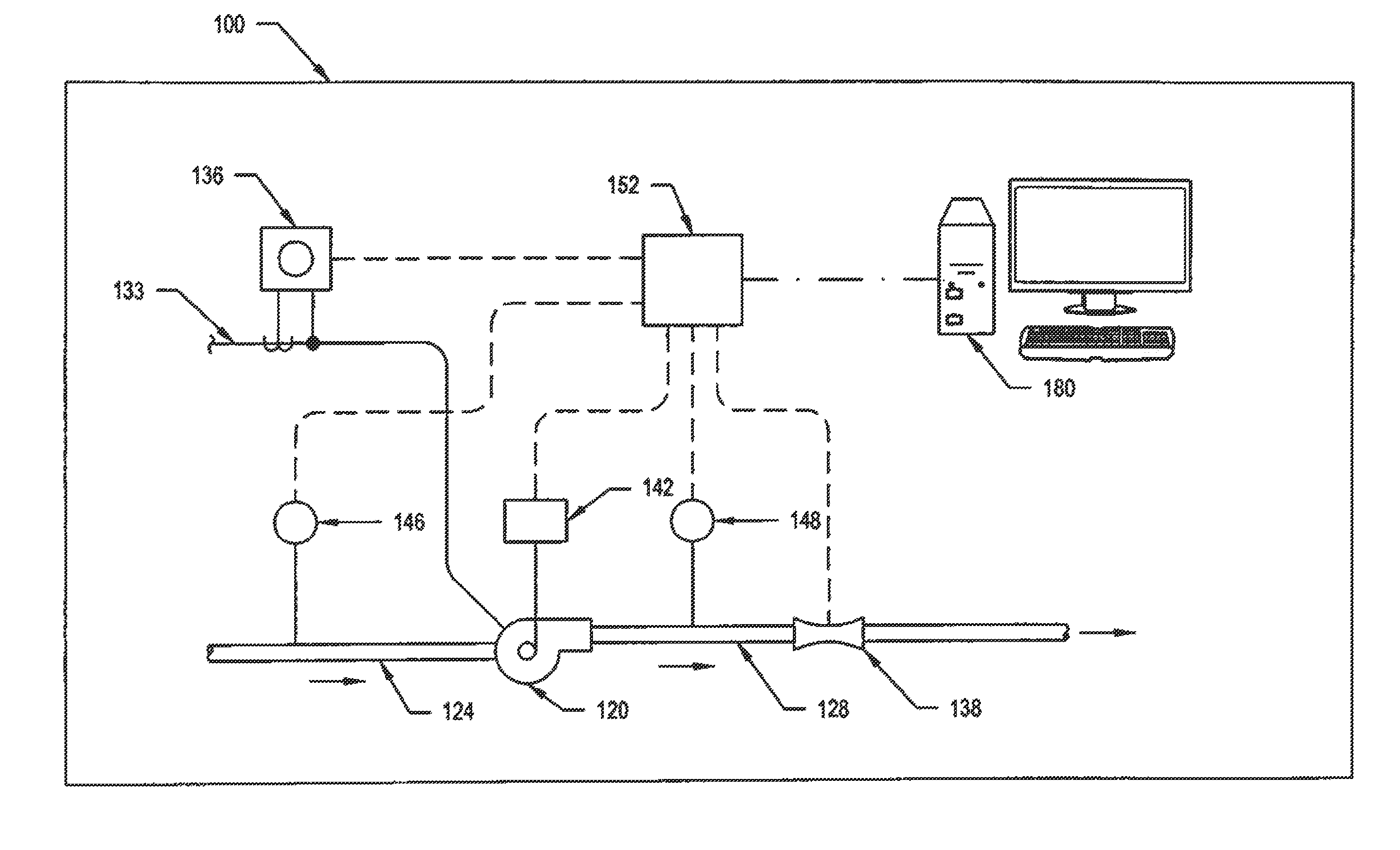
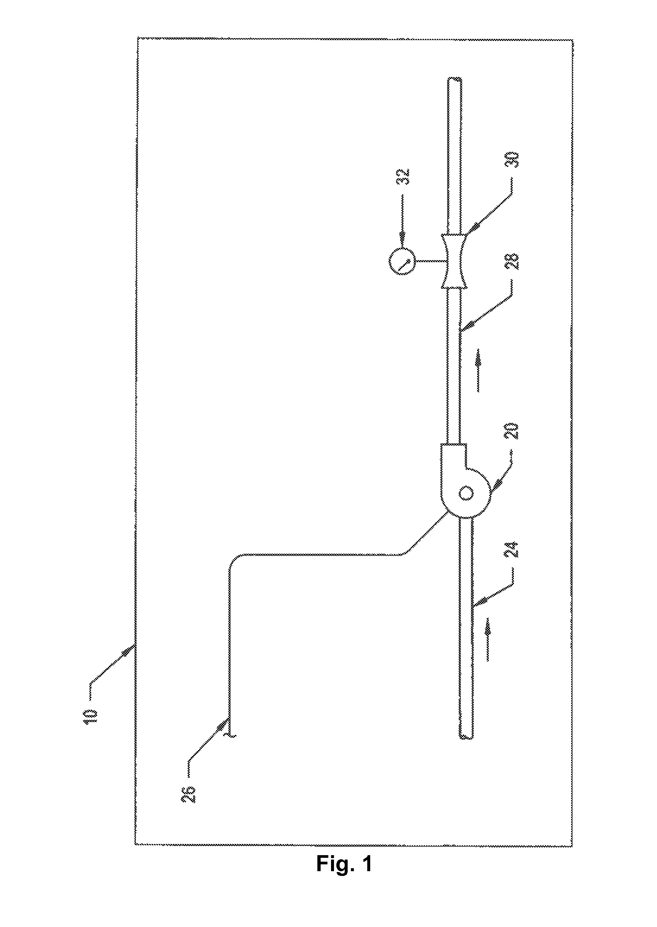
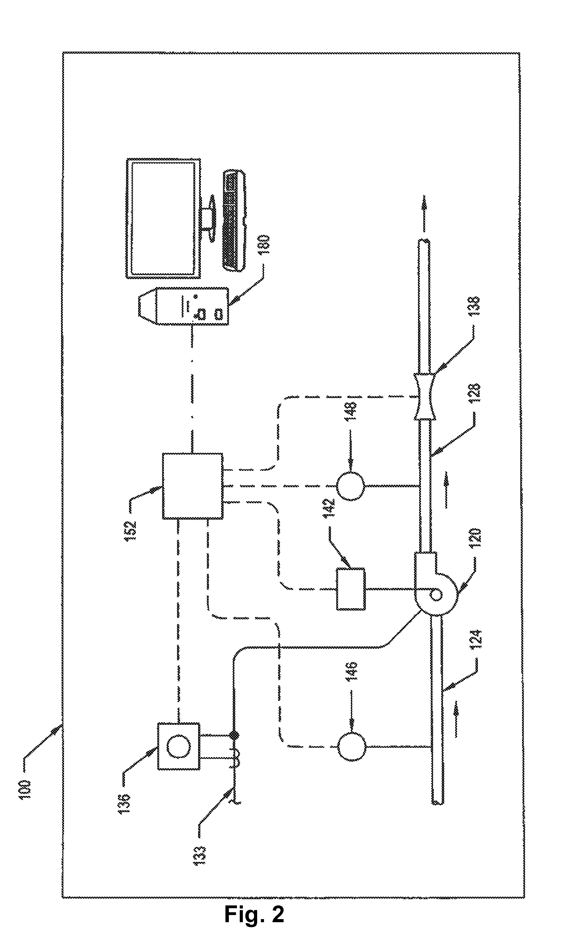
[0110]The following description relates to an exemplary embodiment of a system and related method used to determine pump efficiency / performance in real time. A single generic pumping system / application is described for purposes of this exemplary embodiment, but it will be readily understood that this system and related method is applicable to literally any form of pumping system in which various characteristics of a single or multiple-pump systems pumping incompressible fluid can be measured in situ and in which overall efficiencies of at least one pump of the facility can be determined in real time or periodically. However, it will be readily apparent that the herein related system and method is not limited to specific applications or fields of use. To that end, the herein described system minimally realizes applications such as potable water and waste water treatment plants within the water sector, nuclear gas and electricity plants within the power sector and oil drilling and ref...


PUM


Abstract

A system for measuring real time efficiency / performance of at least one pump in a plant or other facility includes a plurality of monitoring devices disposed in relation to said at least one pump to measure power usage, pump speed and flow characteristics of the at least one pump. A processing system is configured to receive input signals from the sensors in which the efficiency of the at least one pump can be calculated based on the sensor inputs in real-time. The processing system can also compare the calculated pump efficiency values with a user defined set point or threshold or compare to the expected pump performance.

Description

TECHNICAL FIELD[0001]The subject matter disclosed herein generally relates to pumping systems and more specifically to a system and related method for providing in-situ determinations of the performance of at least one pump, for example, a reciprocating or centrifugal pump, which is provided for use in a pumping facility. In-situ performance determinations can be compared to expected characteristics of the pump, thereby enabling system operators to be proactively alerted as to declining performance of at least one pump.BACKGROUND[0002]Pumping systems that are used in a range of industries, including the water, power and oil sectors, may not operate at maximum efficiency due to damaged and worn impellers, pitted volutes, bad motor windings, poor couplings and poorly commissioned pump controls, among other factors.[0003]In most of the foregoing situations, these operating issues cannot be visibly detected and in fact may not be discovered until after the pump has already been taken ou...

Claims


Application Information

Patent Timeline
Patent Type & Authority Applications(United States)
IPC IPC(8): G01M99/00F04D15/00F04B51/00
CPCG01M99/008F04D15/0088F04B51/00
Inventor DEVINE, THOMAS W.DIMINICH, ALISSA J.WEISS, ANDREW JAMES
Owner GHD PTY LTD
Learn More